Radio Rocket V3 (Name TBA)
It’s time to bring everyone up to speed on the latest radio rocket developments!
If you’re interested in some of the nerdery in regards to details about how V2 went, I talked about it on Episode 184 of the Ham Radio Workbench. It was a long conversation, so best bet is to have a large yard to mow, or a long drive to make, while you listen :-)
I still intend on doing at least 1 more launch of Ohyo as well, but there were enough learnings and things that I wanted to change, that I decided to just jump in and start building version 3. The ultimate name is picked, and will be announced once the actual rocket is ready to fly:-)
Major Changes for V3
The Rocket
Version 2 of the rocket was a scratch build, and was frankly, over-engineered. I built it with the idea that if I ever pursue high power certification, I wanted it to be strong enough to handle the largest motors that would physically fit. What this meant though, is that it ended up much sturdier (and heavier) than is really required for the G sized motors I can currently fly (Model Rocket Motor Classifications).
With this in mind, we’re flipping the design methodology, and going with the smallest/lightest design than can handel G motors. To accomplish this, we’re basing the new rocket off of a mid-power Kestrel Kit from Apogee components, which will be modified as needed (likely a slightly longer payload section) to suit our purposes.
The Electronics Sled
The V2 electronics sled was basically a piece of wood with an off the shelf micro controller and breakout boards screwed and glued to it. The discussion during the Ham Radio Workbench interview above helped me nail down a couple decisions I had been waffling on, which was to:
- Do away with the wood sled, and make custom circuit boards/carriers
- Make it modular so that I can plug/unplug and mix and match a combo of off-the-shelf boards, and custom designed boards.
After a couple weeks of deciding how to approach this, this is the current state of the new design:
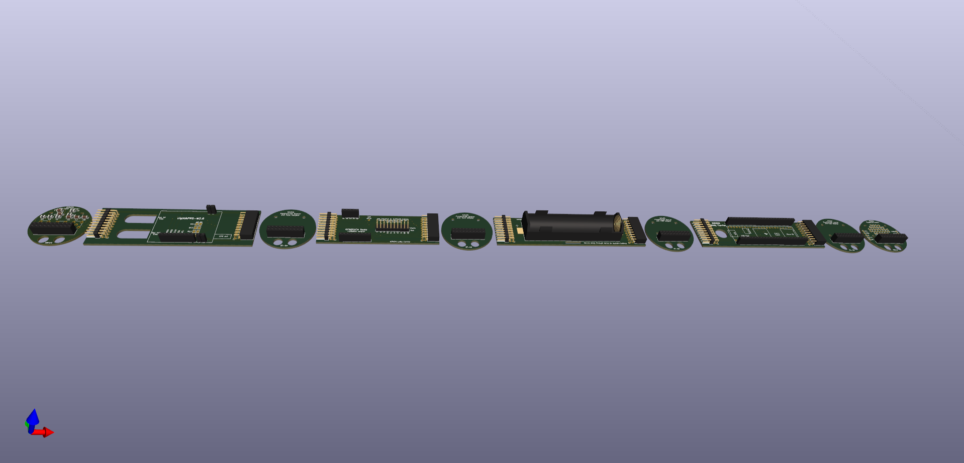
The circular boards can be plugged directly into each other to be stacked, and the rectangular boards can plug in between two circular boards, to carry things that are too large to fit on the small diameter circular boards. there is 20 conductor ‘bus’ that is common across all these boards, which brings a sampling of the micro-controller’s pins to all of the modules.
This initial group of boards is, from left to right:
- (Circular) Antenna mount and VHF/UHF diplexer (so that 2m APRS and 70cm LoRa can share an antenna)
- (Rectangular) LightAPRS carrier module
- (Circular) Connector/tube spacer (different diameter spacer boards can be made to accommodate different diameter rockets)
- (Rectangular) LoRa module carrier
- (Circular) Connector/tube spacer
- (Rectangular) Battery Module
- (Circular) Connector/tube spacer
- (Rectangular) Teensy 4.1 micro-controller carrier
- (Circular) Connector/tube spacer
- (circular) Breakout carrier (which in turn will carry a small stack of Adafuit Breakout Modules)
Some random design notes so far:
- The battery module has a magnetically activated switching circuit on the bottom, so that everything can be powered up after it is in the rocket, by holding a magnet to the correct spot on the outside of the rocket. (Thanks VE6LK for that idea!)
- eventually I may want to make fully custom boards so that I have a round stacking board to replace each of the adafruit breakout boards, but for now having a generic carrier to attach them too will let me do some experimentation.
- I’m experimenting with some different pin jumper vs solder jumper arrangements on the different boards, to select which pins on the various modules should connect to which bus line (i.e. microcontroller pin) to connect to, but am hoping to do the bulk of the talking on the bus via I2C.
- My current relay boards should be fine for mid-power, but for high power I’d eventually need to redesign around a transistor switching method the replace the relay, since relays have shock and vibration limits that could be exceeded in a high power rocket. Since I didn’t really use the relays in Ohyo, I might not even bother fabbing the relay boards until I have time to redesign them. Or I might still get them made, because it’s only a few dollars for the boards, and just a small handful of components that are a few cents to a couple dollars each.