NOVEMBER 3 VICTOR ECHO MIKE
  • Blog
  • Events and Activations
  • Diversions
  • About
  • Gallery
  • Contact
  • Links
  • Subscribe
  • Search
  • Blog
  • Events and Activations
  • Diversions
  • About
  • Gallery
  • Contact
  • Links
  • Subscribe
  • Search
NOVEMBER 3 VICTOR ECHO MIKE

ham radio Projects and musings from a (Relatively) new operator

Here Comes HF!

11/28/2015

0 Comments

 
     Over the long Thanksgiving weekend I started working on installing the mount for my HF antenna(s).  The mount I ordered was from breedlove, who makes some pretty hefty mounts - solid brass, aluminum and delrin for the insulating parts.  I chose the mount I did, because it will work with the hamsticks that I already have, that I used on my last vehicle, and it is also hefty enough for the smaller screwdriver antenna's, which I plan to switch to at some point, when the budget allows.  
     To start, I removed the carpeted liner from the trunk lid.  To do that was fairly easy, I just had to pop out the little plastic snaps, pop off the latch cover (already off in this picture), and take off the plastic handle (to the left, not yet removed):
Picture
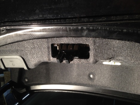
     With the carpeted liner removed, it is easy to see the cross member that runs down the center of the trunk lid (from front to back.)   I knew this was there from peeking in here a while ago, and I had ordered my mount accordingly - normally I would have liked the mount with the 4" base, but that wouldn't fit in the space, so I ordered one of the mounts with a 3" base.  Basically, the support member and the sheet metal of the trunk lid make a sort of tunnel, so I knew the back of my mount was going to have to fit inside this "tunnel."
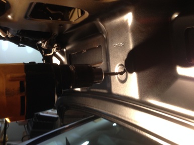
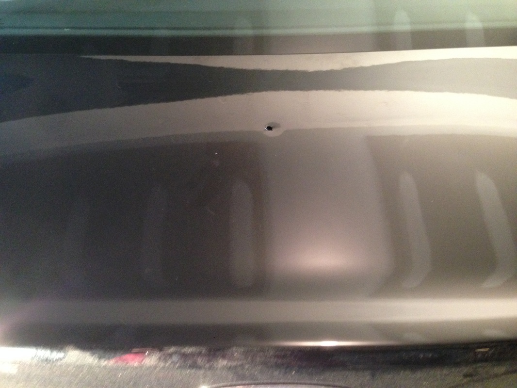
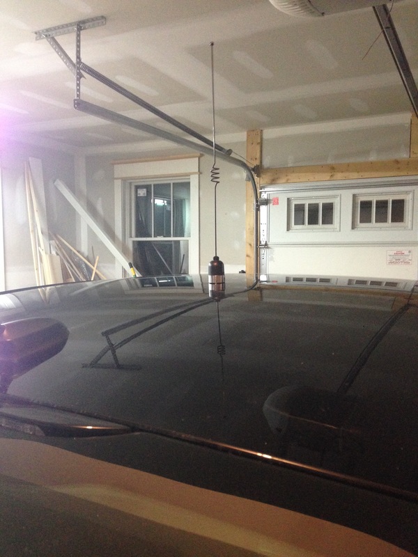
     To drill the holes for the mount, I started by using a factory hole in this "tunnel" that was centered on the vehicle from side to side.  I  chose a drill bit that fit this hole perfectly, that would reach the whole way through to the top of the trunk lid.  I then used this to drill my pilot hole.  Below you can see me lining up my drill from the inside, and the resulting pilot hole as seen on the top of the trunk lid.  The picture of the top of the trunk lid is a little confusing to look at, because you can see the unfinished drywall of my garage ceiling reflected on the closed trunk...sorry for that!
Picture
Picture
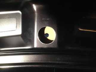
     With the pilot hole drilled, I stepped up to a 5/8" drill bit for the hold in the top, which is what was needed for the center bolt of the mount I used.  I then used a 2 1/2" hole saw on the inside, to create a larger "access" hole to work from underneath the mount.
Picture
     At this point, I was able to install the HF mount using just the center bolt, so that I could turn things side to side, and adjust the ball front to back, until everything was plumb.  To get everything plumb, I stuck the fiberlass bottom section of a 6 meter hamstick into the mount, and used my level against that.  After I had it plumb, I used the mount as a guide to drill the other holes, to lock everything in place.  After tightening all the nuts and bolts down, here's how it looked:
Picture
Picture
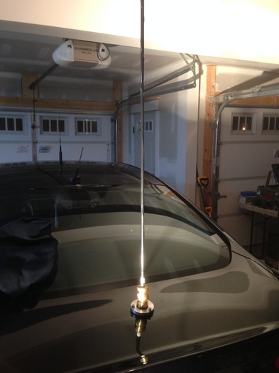
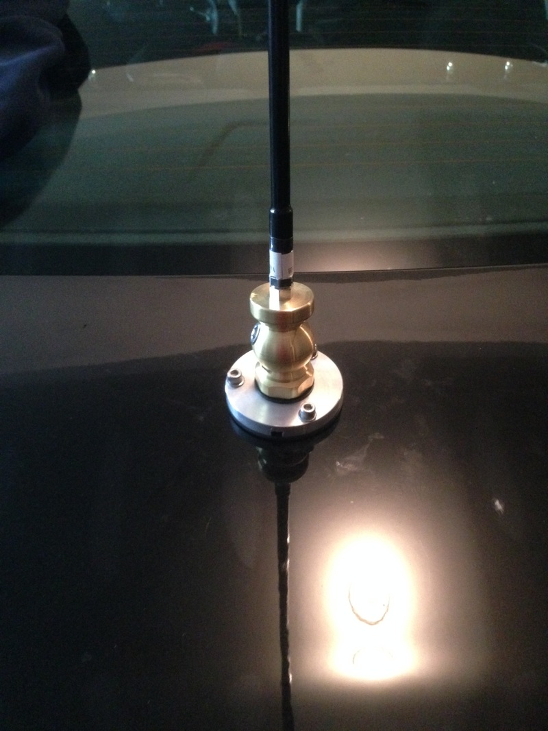
     The morning after doing this, I connected the coax to the mount, and ran it to the antenna.  I covered the coax in split loom and routed it along the trunk hinge on the right, so that it would match the factory wiring that runs along the trunk hinge on the left.  I also then filled the "tunnel" with expanding foam so that it would stiffen everything up, and provide extra stability to help keep the sheet metal on the top from wanting to flex as the wind catches the antenna while driving down the highway.  Before spraying in the foam, I packed rolled up bubble wrap around the edges of the access hole, so that the foam wouldn't cover the antenna connections, or bulge out through the access hole for working on the antenna connections.  As for the type of foam, I used the stuff from the big box store that is designed for large gaps, and holy smokes did it ever do the trick!  I can now grab this mount and shake the whole car, with barely any deflection the sheet metal it is mounted on.
     At this point I have 2 primary things to do, in order to have somewhat decent HF capability in the car.  The first is to install bonding straps between the various sheetmetal parts of the car.  Some of the hardware I need for that I ordered from Amazon today, so that will probably be a project next week sometime.  Once the bonding is done, I can do final tuning on the antennas.  At that point I'll have working HF......but I'll be far from done with this project.  Check back soon to see what's coming!
0 Comments

It Works!

11/25/2015


     Today after work I stopped at a small communications company to buy some RF connectors so that I could connect the antenna I mounted on the roof of car.  Because I was driving around for work, and wasn't going have time near my soldering iron anytime soon, I asked what they would charge to install it for me.  They ended up only charging me about $10 for the connector, installing it, and for one additional adaptor that I needed.  Awesome! The guys that did this for me were the folks at Lentini Communications.  I was told about their shop by a fellow ham, while talking on the New Haven, CT machine.  With the antenna now connected to the radio, I decided to grab the audio adapters I needed to finish connecting the radio's audio to the car's audio.  
​
     With that thought in mind, I made a quick trip to Radio Shack.  The audio extension cable that comes with the Yeasu head seperation kit plugs into the radio, and leaves you with a 1/8" female mono jack at the other end.  I needed to get from this, to the 1/8" stero female jack that every ford I have driven in the last 6 years had.  I ended up picking up a connector pack that had a 1/8" mono plug on one side, and a 1/8" stero jack on the other side.  I then grabbed a short 1/8" male stero to male stero cable.  Perfect!.....Until I went to the car.  I flipped up the center console lid (because that's where Ford puts the Aux Jack) and - what the heck!  No Aux jack!  I looked all over and couldn't find it.  I grabbed the manual for the car.  The section about the radio tells you how to select the aux input using the radio, but doesn't tell you where the aux input jack is.  What the heck.

     I ended up checking with Google, and apparently I'm not the first person who has had this problem with their 2016 Ford Fusion.  Apparently on many models and packages, there is no aux jack - just the USB jack for connecting an iPod, iPhone, or something similar.  I turned around and took the connectors back in to Radio Shack and returned them.  After some parking lot considerations, I came up with plan B.
​
​     I drove across town to Best Buy and bought one of these:
Picture
     It is a basic bluetooth transmitter.  The idea is to use this to take the audio from the radio, and transmit it to the SYNC bluetooth system in the car.  After buying this, I realised however, that this has a stero plug on it, and I still needed an adapter to get to the 1/8" mono jack so........

Picture
     Back to Radio Shack again for this.  I actaully only needed the connector in the upper right, but they don't sell them individually (in the store anyway.)  I'm sure I'll find a use for the other ones...even if it is just to fill up space in the junk drawer.

     Even though it was plan B, the good news is that I now at least have the radio installed, with a working antenna, and working audio.  I made a quick contact on a local repeater, and was told I sounded good - only note was that my audio was a little loud, so I backed off the mic gain.  The next major peices of the project will be getting the antenna stuff installed for HF.  As always....stay tuned!

Progress

11/22/2015

0 Comments

 
     Progress is a wonderful thing!  When I last left off I had managed to essentially run some wires.  Over the last couple days I managed to get a couple things done that actually look like progress too!  If you recall from my post on 11/6, I stated that I was planning on using the empty space under the climate controls for mounting the control head of my Yeasu 857d.  
Picture
     I wanted to make a template first, so I started by roughly measuring the size of the opening, and then I cut some scrap hardboard that I had into the shape.  I did a test fit, then recut, test fit then recut.  I ended up making about 4 of these before I had one that fit the opening the way I wanted it.  After this peice was cut, I used the parts that I was intending on mounting on it to mark and make my next cuts.  These parts were the jack for the  microphone, and the bracket that holds the control head.  Once that was done, my template looked like the picture below.

Picture
     I actually cut out the shape of the head bracket, because the plan was to recess it into the part a little bit, so that the control head doesn't look like it is sticking out so far.  I mounted everything into the template peice, and test fit it into the car.  Looking good!

Picture
     The Yeasu seperation kit comes with an extension cable with RJ45 connectors on each end.  At the end where the mic is supposed to attach, they provide a female-to-female connector.  Instead of using this connector, I found a female-to-female bulkhead connector on e-bay.  This makes for a clean and professional looking mic jack.  With good thoughts on the fit of the template, it was time to transfer to the material that will actaully make up the part.  I wanted something plastic looking, with some texture, to kind of blend in with the other dash  components.  Luckily, I had been thinking ahead.  Remember that trip to IKEA I took  with the YL a couple weeks back?  While there, I picked up two of these for less than $2 each, and they were the perfect material and texture.

Picture
Picture
​

    While running around this weekend, I also grabbed a couple new mic mounts at radio shack so I could play around with where to stick the mic.  After painting the part, and mounting the mic, it looks like this:
Picture
So far I'm pleased with how this is turning out.  Today, I also mounted the radio body in the trunk.  No pics of that yet.
Picture
     The main reason I don't have pics of the trunk mounted radio body is because the location it is mounted right now it only temporary (it's screwed to sheet metal, so temporary doesn't mean lazy in this case!)  This project will have a "Phase 2" that will be revealed as I go, but while I work on that part, I want to have a functioning mobile setup!  With power connected to the radio body, things are looking good up front.  I snapped a couple pictures after dark too, for effect.
Picture
 Here is a view of both the radio and mic, all mounted up.  In case you arer curious about the text on the radio screen - thats W3RRR, the local radio club that I am a member of.

Picture
     This is a similar shot, but at night, with the flash off.  I just though the effect was cool.  The Yeasu actually blends in pretty well, after picking a display color that is a close mach for the dash lights.

     So whats next?  Well, audio for one.  The plan is to feed the radio's receive audio into the car's audio system.  I've done this in my other Fords, so it's an easy task - I just want to get a couple different connectors than I used in the past to keep the wiring cleaner. I also need to put a connector on the coax coming down from the rooftop antenna.  I started that tonight, but botched the job, so I cut the connector off. I didn't have time for attempt 2 this evening.  I also have a mount ordered from Breedlove that will be the mount for my HF antenna(s), that will get installed once I get it.  There are several other tidbits, and bits and peices that I will keep working on as well, so check back soon!
0 Comments

Grrrrrrr.....

11/16/2015

0 Comments

 
     So.......I've had my car just over a week, and someone hit it already!  Based on the location and type of damage it looks like someone hit it in a parking lot.  I was in Pittsburg PA, Rochester NY, and Philadelphia PA this past week, and while I was in Philly it was valet parked, so who knows when it happened.  Oh well.  I took it to the body shop for the estimate today, and as soon as they get their estimate put together it'll get fixed up like new - that's what we get insurance for.
     Now that the bad news is over - here's some random news - this weekend I was putting the "ham" in ham radio operator.....my family does their own butchering every year, and for the last 20 or so years we've done it as a demonstration of 19th century butchering techniques at a living history farm in New Jersey.  If you happen to know me personally, you might be able to find me in the picture. 
Picture
       Anyway, enough of that - I'm sure you're more interested in my progress on my project.  I had a little bit of time to work this evening before and after my daughter's swimming lesson.  I started by popping off the door and moulding trim on the drivers side of the vehicle.  With this done, I was able to peak up between the headliner and the roof of the car to see what was up - looked straightforward enough. ​After having a peak up there, I ran a peice of painters tape across the top of the car, from side to side, and measured to find the centerline of the vehicle.  On my car this turned out to be 1' 10 3/4" from the side of the vehicle (just in case you cared....)  

Picture
     After marking the center, I put down a bunch of tape around the area I intended to drill, and then taped the end of the hose of my small shop vac right at the location of the future hole.  This way most of the metal shavings would get sucked up as I was drilling.  Once the hole was made (I used a 3/4" metal hole saw), I also used the vacuum and sucked up every speck of dust that even looked like it wanted to pretend to be a metal filing.  I found out the hard way with my old vehicle that if you don't get all these off you end up with little rust spots.  With the hole made, I followed the dirctions that came with the Larson NMO mount to fish the coax through the hole and attach the mount.  I ran the coax down the rear pillar (being carful to route the cable away from the airbags!) to the location in the trunk where the radio body will be mounted.  Just a small amount of snugging with the wrench and presto!  A rooftop NMO mount.  I stuck an antenna on it for a quick pic also.  I don't think this is the final anteanna I will use, but it's one I had laying around (that also happens to clear my garage doors.)

Picture
     I'm pleased with how it turned out....what do you think?  While I had the trim moulding off of the drivers side of the vehicle, I also used the opportunity to route the control, mic, and audio cables needed for remotely mounting the control head of my radio - a Yeasu 857d.  (It's actaully the radio that right now can be seen sitting on my desk in my first post!)

Picture
0 Comments

Ouch!

11/8/2015

0 Comments

 
      Well, it's 12:30 UTC (that's 7:30am for those of us who live on  the East Coast of the US.)  My hands are still aching from last night, but I had to get up and share what I accomplished yesterday on my new 2016 Ford Fusion.  It doesn't look like much, but it's the part of any radio install that I dread.  For many, the dreadful part is drilling holes in new body work.  For me, the battle is finding a place and a way to get power wires through the firewall and routed to the location of the radio.  Last night, that battle also involved 2 sliced fingers, a sliced knuckle, and just a little bit of blood.  Ouch!
     I started the project last night by popping off the trim at the front passenger side of the car, so that I could pull back the carpet from the firewall. I looked to see what I could see - I was hoping for an unused grommet or some easy place to fish the power wires through.  No dice.  I got out and looked at the same area from the firewall side.  Nothing.  I got back in and looked some more.  I got back out and looked again - still nothing.  I'm not sure how long this went on, but you get the idea.  I was really hoping to find an easy, exisiting, location to get wires through here because of how much room there was in the engine bay on this side  - oh well, that would have made things too easy.
     I finally gave up, and moved to the drivers side.  After some reaching, bending, and twisting around I was able to find one of the factory wiring harness pass throughs, and it seemed pretty roomy...awesome!  In the engine bay, this turned out to be right behind the battery, so I undid the battery hold downs and slid the battery forward a little bit to get myself some additional room.  To get the wires fed through, I did a fancy trick that I either made up, or read about and didn't remember.  I proceeded to grab an old coat hanger, cut it into a straight wire, and poked it through from the inside out.

Picture
Bingo! There's the other end of my "fish-wire".  I attached my power wire to the other end of this and pulled it through.  I had to pull pretty hard to get the end of the zip cord to widen the hole in the grommet enough for it to pull through, but after that it was easy going!

     Here's my spool of wire on the inside of the car, fed up through the grommet.  Sorry for the weird lighting - the lights I use to be able to see my work do strange things to my iPhone camera as it tries to focus.
Picture
     Before doing anything else, I cleaned up the wires in the engine compartment.  I added 2 fuse holders (one for the negative and one for the positive.  I also dressed the wires with splitloom, and slid the battery back in place. Most people probably wouldn't know I even added anthing now that its all done!  (Except for maybe the couple extra fuse holders that you might able to find, if you look closely.)
Picture
Just a note here - All the big manufaturers tell you to connect both positive and negative leads directly to the battery.  I actaully connected my negative to the "jump point" as outlined by the ​​K0BG article on wiring because this car, like many new ones, has some fancy "stuff" in the negative lead for system monitoring, that you end up bypassing if you connect straight to the battery.

     My bad on this next one - I didn't take any pictures while I had the trim off and the carpet rolled back.  Basically, I took the door sill trim off, rolled the carpet back, and ran the wires along the channel underneath.  Once again, sorry for the weird lighting in these pics.
Picture
Picture
Picture
   All that to get the wires here, in the trunk.  As you may have guessed by where the power wires are routed - the radio body will be getting installed back here. These will get tucked behind the upholstry for final routing, when the time comes. ​  At this point, you may also notice that there is an extra pair of power wires popping out.   There will be a distribution block back here, and I pulled an extra pair of power wires from the trunk, back to the front, for a small CB radio that will end up getting installed.  
​     Oh No!  Did he really say CB?  What honest ham radio operator has a CB, let alone calls it that?  Well, this one I guess.  Because of the amount of time I spend on the road, I like having a small CB, which pretty much always stays on channel 19.  Often, I don't even have a mic connected, but I like being able to flip it on when I'm getting into weird traffic stuff in other cities - the truckers always know whats up, and are usually talking about it when the traffic is bad.
     For those who are curious, I used an app called "Circuit Wizard" by Blue Sea Systems to decide what gauge of wire to use.  It's pretty slick actaully - you put in all kinds of specs on the equipment, the wire, the type of install (does it go through an engine compartment) and it spits out what gauge of wire you should be using.

     So whats next? I supposed I might tackle drilling the hole for the NMO mount on the roof next, or I might work on routing the cables needed for the remote mounting of the radio body.  Stay tuned to find out which!  

​     P.S.  For those who know about my home shack project, the next step on that will be more concrete sealer (just to make sure the cat smell is gone for good) and framing up some walls.  My next weekend that isn't already full of stuff will probably involve a trip to Lowes for some lumber.
0 Comments
<<Previous
Forward>>

    Categories

    All
    Antenna
    Cw
    Digital-modes
    Flying-with-gear
    Home QTH
    Miscellaneous
    Mobile
    Operating Events
    Portable
    POTA
    Shack Build
    Technical


    - N3VEM -

         Welcome to my Ham Radio Blog!  This blog was started primarily to share my two concurrent shack builds - my mobile station and my home station.  Over time, this has grown to include sharing about my operations, and general radio-related thoughts that I have as a newer operator.  
         
    ​Enjoy!

    RSS Feed


    Picture
    POTA!

    Picture
    Proving that hams do indeed still build stuff!

    Picture
    100 Watts and Wire is an awesome community, based around an excellent podcast. 

    Archives

    September 2020
    July 2020
    January 2020
    September 2019
    August 2019
    July 2019
    June 2019
    May 2019
    March 2019
    January 2019
    December 2018
    November 2018
    October 2018
    September 2018
    August 2018
    July 2018
    June 2018
    May 2018
    April 2018
    March 2018
    February 2018
    January 2018
    December 2017
    November 2017
    October 2017
    September 2017
    August 2017
    July 2017
    June 2017
    May 2017
    April 2017
    March 2017
    February 2017
    January 2017
    December 2016
    November 2016
    October 2016
    September 2016
    August 2016
    July 2016
    June 2016
    May 2016
    April 2016
    March 2016
    February 2016
    January 2016
    December 2015
    November 2015


Picture
Copyright © 2015
 Vance Martin is a participant in the Amazon Services LLC Associates Program, an affiliate advertising program designed to provide a means for sites to earn advertising fees by advertising and linking to amazon.com.