NOVEMBER 3 VICTOR ECHO MIKE
  • Blog
  • Events and Activations
  • Diversions
  • About
  • Gallery
  • Contact
  • Links
  • Subscribe
  • Search
  • Blog
  • Events and Activations
  • Diversions
  • About
  • Gallery
  • Contact
  • Links
  • Subscribe
  • Search
NOVEMBER 3 VICTOR ECHO MIKE

ham radio Projects and musings from a (Relatively) new operator

Filling the Holes

4/18/2018

0 Comments

 
Post Contains Affiliate Links   
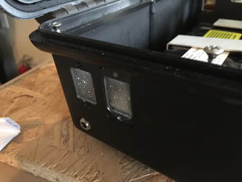
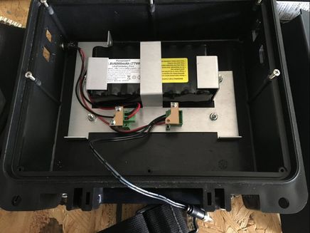
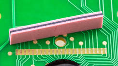
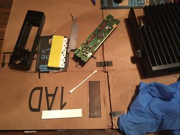
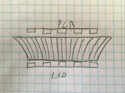
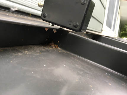
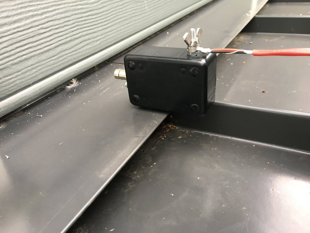
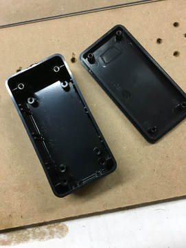
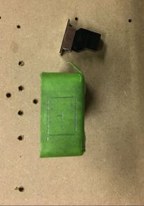
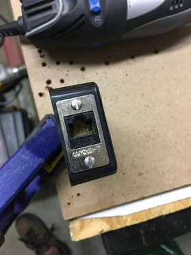
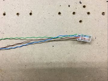
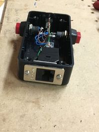
    A couple of weeks ago I pulled one of my on-going projects (the crowd-sourced one) off the pile and did a bit of work.  To bring anyone up to speed who hasn't been following along, I've been working on a project using a Seahorse box that, in a previous life, housed electronics associated with my work.  As I've been doing this, I've been getting input from my readers on each step along the way.  Last time I mentioned that I was pulling out all of the old bits that wouldn't be needed, to get ready to put the new stuff in it.  That left me with some holes:
Picture

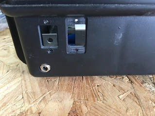
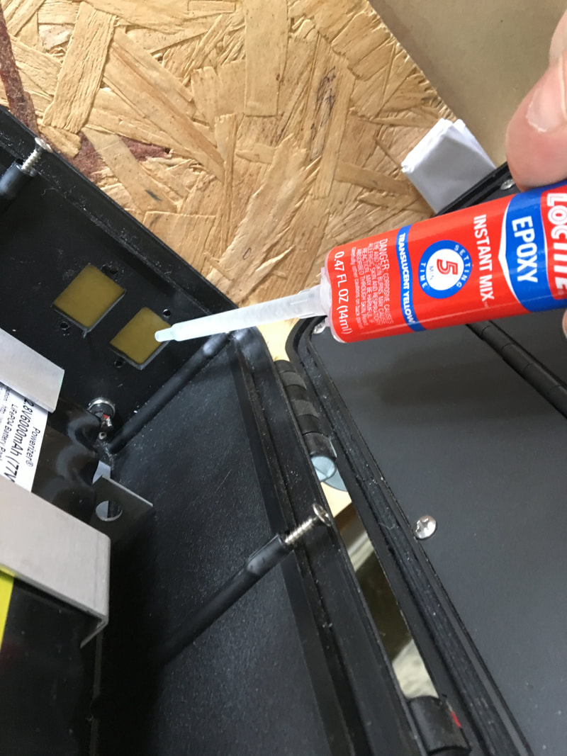
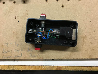
     The power jack I'm going to leave in, because I'll reuse that to connect the charger to the built-in battery (which I'm also re-using from this box's prior life.)  This just left me with the other holes to contend with, and last time I promised that I would share my trick for doing that.  Big reveal:
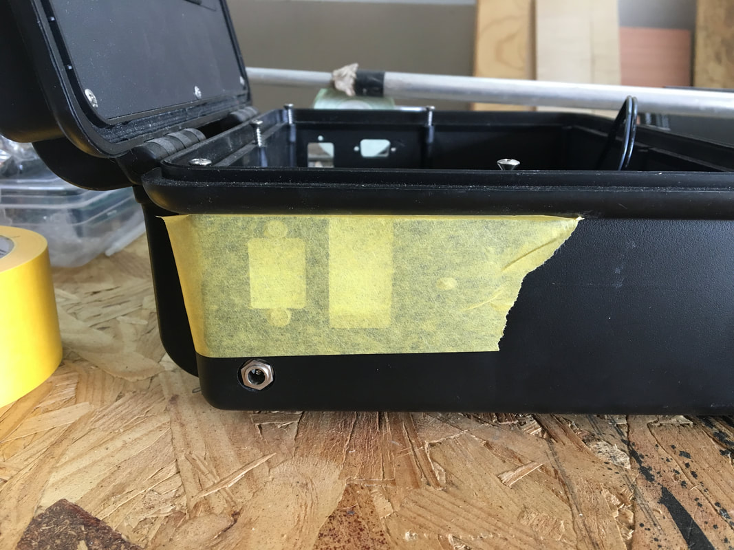
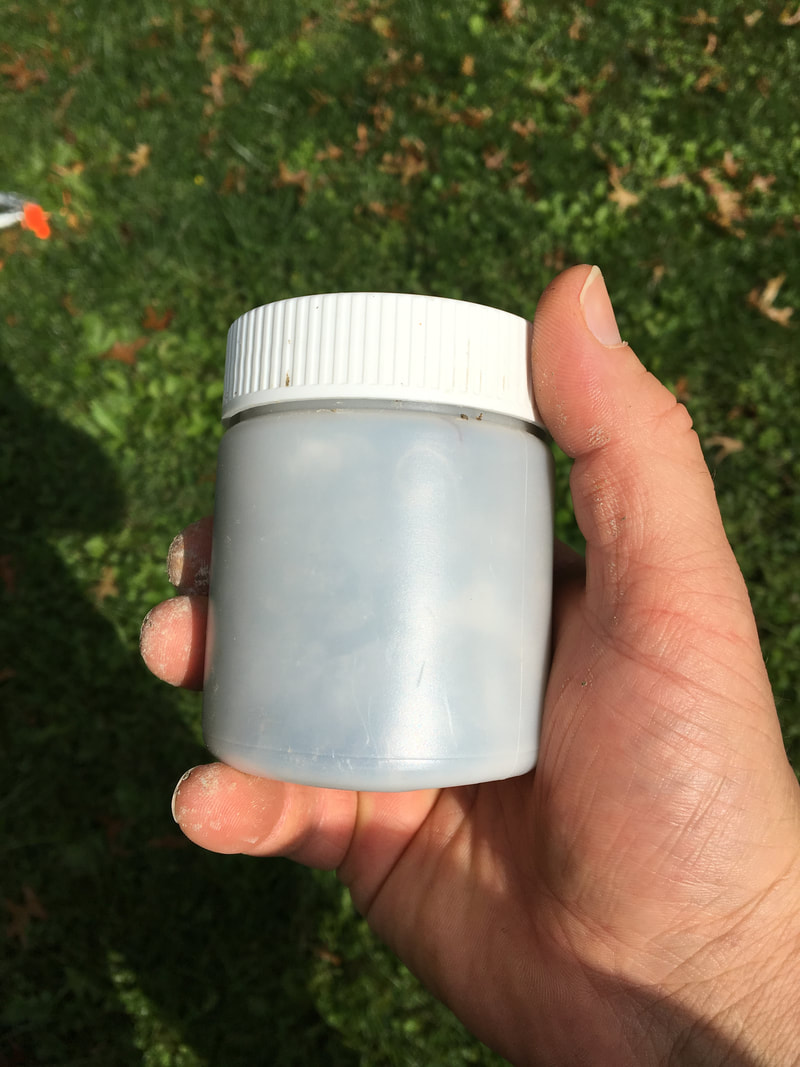
​Epoxy.
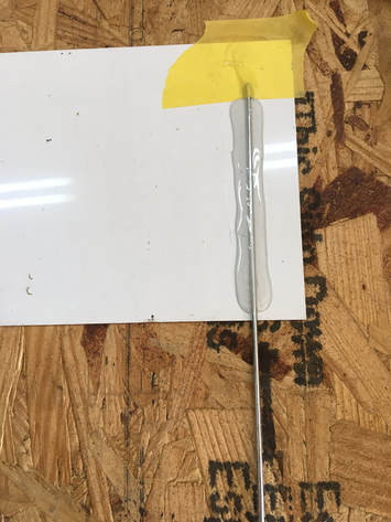
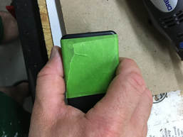
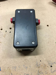
     For something that will be painted or covered with something else, liquid epoxy is an easy way to fill in a hole.  In a situation like this, I just cover one side with tape, sit the item up on end, and fill the void.

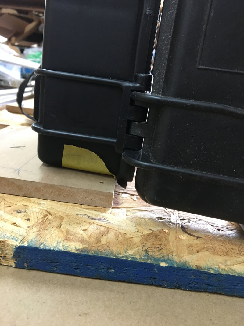
     Once the epoxy dries you've got some fancy little windows.  Hit them with a bit of paint, or cover them with a decal of sorts (like I'll be doing with this one) and you're back in business!
Picture

P.S.    If your YL has a little metal yard sign that you busted when you snagged it with the mower wheel, use any left-over epoxy to fix that too.....
Picture
Back to Part 11
Part 13 Coming Soon!
Back to Part 1
0 Comments

Remember This Project?

4/4/2018

1 Comment

 
Remember the crowd-sourced project I was working on? You know - the thing where each step along the way I asked all of you for your ideas and input? Well, I haven't forgotten about it!

I've had several major things going on (one of them being finishing up my Information System degree - 5 weeks to go!) Anyway, because of my busy schedule I've just been picking away at all my various projects a little bit at a time. This week, I managed to steal a few minutes in the garage while the kids were chalking on the driveway to work on the box the project is going into. For now this consisted of removing all of the old stuff from the box that isn't being reused, which left me with just the battery from it's prior life:
Picture

     With all the old parts out of the way, I'm just about ready to start mounting up the parts of my Bitx40 that are going in here.  The only real thing to do before I start that, is to fill in the holes that were left by removing the old connectors - the next time I get to spend a few minutes on this project I'll show you my trick for doing that :-)

​     73 for now!
Back to Part 10
Part 12 Coming Soon!
Back to Part 1
1 Comment

Elastomeric Carbon Zebras

1/10/2018

0 Comments

 
Say what?!
Picture
     No, I haven't completely lost my mind and started genetic experiments to try and create stretchy wildlife that will transfer an image from one sheet of paper to another (remember carbon paper?)  These are all words that apply to a type of connector that I didn't have much familiarity with until a couple weeks ago, which also happen to be present in a lot of electronic devices - including our ham radios!

     To some folks this might be old hat, but for me it was another learning experience that I'd like to share, because I'm sure there are other people out there like me, always learning new things.  With that little tidbit, here's my story - enjoy!
     One of the local club members had a radio that didn't seem to be making proper contact for the mic, because it wasn't always keying up, or would key up, but no audio would be transmitted, etc.  In the process of plugging the mic in and out to try to figure out the problem, the little retention clip on the RJ45 plug broke off, so he needed to put a new plug on his mic cord.  I helped him put the new plug on, but the mic jack was still being finicky.  I decided to take the radio apart to see if the mic jack was one that could be easily removed from the board and replaced.  After doing that, taking pictures to see about ordering a new jack, and reassembling the radio, the LCD display had missing segments.  Uh Oh.
     I ended up taking the radio home to spend some time doing battle with it, to get it working again.  Inside the radio there was a lot of oily residue, which I suppose was contact cleaner.  Now, many contact cleaners and oils that are used to coat and clean electronics are non-conductive, but I have learned from something we found at work, that non-conductive liquids can cause problems, because sometimes in the process of them doing their thing, they just move dirt around, and if the dirt gets in the wrong place (like between relay contacts or into pizeo buzzers), it can do strange things.   File away that note, it will come back shortly.
PictureAn elastomeric connector - similar to the one in the radio I was working on.
     In the process of taking the radio apart, I also came across the funny rubber strip (elastomeric connector), often called a Zebra (brand name) connector, that makes the contact between the circuit board and the LCD display.  I've seen these before, but never really messed with one - all I knew was that through some unknown magic it conducted electricity between these two parts.  My gut told me that this magic wasn't happening, so I did a little Googling, and determined that I might just have some dirt or oil (remember that thing I mentioned in the last paragraph...) that was keeping this little connector from working, and that cleaning with alcohol was the ticket.  With that bit of information, out came the rubber gloves, q-tips, and alcohol (isopropyl, not Jameson).  I spent a good bit of time cleaning all the old residue out of the radio.

Picture

     After all the detailed cleaning work the result was.......nada.  Still the same problem.  I figured that maybe the easiest thing to do was to just get a new Zebra connector.  The Icom service manual for the 2100H had them listed with a part number, so I called Icom.  It turns out they don't have parts available for this radio any longer.  My next stop was to see what I could find via the electronic suppliers, but I came up short.  I did happen to stumble on the website of a company that manufactures these things, and does prototyping service, however. I called them in the off-chance that maybe they do some retail sales.
     That's where my luck changed - the guy that answered the phone just happened to be another ham, named Don - what are the odds?!  Anyway, because of the ham-brotherhood he spent some time talking with me about these connectors (the company he works for only does manufacturing for wholesale, or larger orders than I would have been making.)
     Basically, the way these connectors are made, is in super-thin layers.  The first layer is basically just a rubber-like material, the next layer is the same stuff, impregnated with carbon, the next layer is just the rubber-like material, etc.  This means that every other layer is conductive, so you end up with a strip that is something like this:
Picture

     The thing that I found most interesting, that Don explained to me, is that these strips aren't actually completely conductive - if we zoom in on a single strip, at the microscopic level, what we have is something like this:
Picture

     Basically, the little bits of Carbon have to touch each other to conduct electricity, so these connectors have to be under enough pressure to squeeze them all together, but not so much pressure that it deforms the strip and causes things to make / not make contact where they are / are not supposed to.
     Don also explained to me, that these strips can unfortunately have a "memory" so sometimes after being in use for a while, they don't really go back together like we'd expect.  Also, because of the nature of how these strips work, they need to be supported as you put things together, so that they line up properly.  In the case of the Icom rig, there are plastic pieces that go in place around this strip to hold it, but from this conversation, I realized what my problem was.
     Whether it was from manufacturing, or from "memory" over time, the strip in this rig was actually too long, from side to side.  If it was this way from the start, the machines that assemble the radio probably do all the hard work, and kind of "force" the rubber down to the size needed as it is assembled.  Regardless of how it happened, I could tell by looking at the strip (and measuring it) that it was several mm too long.  When I put it down into it's slot, I had to force the bottom, which made the sides flare out, giving me something like this:
Picture

     Pretty obvious now what was going on, isn't it?  With that bit of knowledge, I trimmed the strip down to it's proper length, put everything together, and presto:
Picture

     As a side benefit, I think some of the oil and dust mixture may have been the root cause of the mic connection issue as well, because after finally getting everything clean, and back together, the radio is working like new.  In the true ham-spirit, the whole repair didn't cost anything other than my time, so everyone's wallets are happy as well!
     P.S.  As a side note - I wouldn't recommend randomly cutting connectors down if you have the same problem - I have to assume that most radios come from the factory with everything cut to the proper size - this was probably just a fluke.  If you have similar issues though, you can try cleaning the ends of the connector with alcohol, using small strips of tape to "shim" around the connector (another tip from Don!) to help it stay in the right place, use tape or washer shims under/over the boards or to help the board put additional compression on the connector, etc. You get the idea - whatever it takes to hold the thing in place, and make sure there is enough "squeeze" to make the little carbon atoms touch each other!
0 Comments

Wire in the Air

9/15/2017

0 Comments

 
Post contains affiliate links.  ​
Within the last several days I shared the little 9:1 unun that I made for myself - if you missed it you can check it out here. This evening (well, that is the evening I started writing this - who knows when I'll finish and publish it!) I used the little unun to put some wire in the air.
I had a spool of left over cable from extending my fire alarm system into our addition when we did that project, so I cut off a length of it for my random wire. There are actually a couple neat resources available for knowing what lengths of "random" wire are likely to work best, but I used the info available here and decided to cut my wire at about 36 feet, to use on 40 - 6 meters.
I actually soldered all the wires in the twisted shielded pair together at the ring terminal, so really the shield of the cable is probably doing most of the RF work. Anyway, after I cut it and put a connector on, I hooked one end to my fence out front, and connected the other end to my unun. Without connecting a counterpoise or ground I scanned from 0 - 30 Mhz with my Rig Expert AA-54 to make sure I was in the ballpark. 
Picture
The scale of this graph isn't great, because it tops out at an swr of 5:1, but in the amateur bands, everything above that was at least under 12:1 or so.  I figured that once it was in the air, it would probably still be in line with something my tuner could handle, so I started working on getting the wire up.
Since this is a temporary antenna, I didn't want to get crazy with buying stuff to hang it up.  I've usually got mason's line around because I end up using it for projects around the house.  I needed something however, to get the end of the line over a tree.  Thanks to my bad grammar, when I posted the statement on Twitter that I was looking for something to use,I made it sound like I wanted to throw my garage over a tree...thanks to VK5OI for catching that :-)
Anyway, I ended up finding a little plastic bottle (my YL says it was from bouillon) so I filled it with gravel, tied one end of the string around it, and threw it like it was going out of style (and got it on the first try!)
Picture
Picture

Those of you that read my first post on the topic may recall that my intention with this little 9:1 unun and random wire was to use the metal roof of our addition as that counterpoise.  Rather than try to figure out a way to mount the unun, and then add a way to connect a jumper wire from the unun's ground side to the roof, I came up with something to kill both birds with one stone.
At the top of the metal roof, there is a lip that covers the roof-to-wall connection.  I drilled a small hole in the edge of this (in a spot that any water running through the hole, would just land on the metal underneath, and run down the roof.)  It was then simply a matter of sticking the counterpoise lug through the hole, and spinning the wing-nut on from the bottom (I used a star washer on the bottom to make sure I pierced the paint and got onto the bare metal.)  This accomplished the job of holding the unun in place, AND making my connection to my giant counterpoise! When I take it down I can always caulk the hole if I really feel its necessary.
Picture

I connected my antenna wire to the other terminal, and then looped the other end through an insulator.  With those details done, I tossed the end off the roof to the back yard where the end of my mason's line was waiting patiently.  Once I tied it off, I walked around to the other end of the line that was waiting for me on the other side of the tree, and hoisted the whole thing into the air!
Picture
Picture

I'm not too worried about wind, trees, etc. pulling on the wire, because mason's string is not strong stuff - at a moments protest it will just snap, letting the wire drop with no harm to the roof or house, so no worries there!  In order to give it a little wiggle room however, so it wouldn't snap in a light breeze, I didn't tie the other end off - I just used a super high-tech counter-weighting arrangement:
Picture

Remember when Costco sold Scoop Away cat litter in buckets?  That was great for two reasons - afterwards you had a useful bucket AND the buckets were a recyclable plastic.  Now their litter comes in plastic bags that are much less recyclable.  Boo on you Scoop away!

Anyway, in the bucket is half a brick to give it some weight.  In a prior life I had drilled holes in the bottom of this particular bucket, so it won't hold water and get funky!
With the wire in the air, this was the new view out of the window at my temporary operating position:
Picture
When I first put the antenna analyzer on this however, things didn't look so hot - some of the bands were so out of wack that my little LDG YT-100 tuner wasn't going to have a hope of tuning it.  I made a wild guess that because of the angle, with the metal roof directly under, I was getting some unexpected interaction between my radiating element and counterpoise.  To address that, I went to another standby in the temporary antenna arsenal - bungee cord.
Picture
Picture

This gave enough separation that the SWR curve across my targeted portion of the HF spectrum looked like something my tuner would handle!  40 meters was the worst at 8:1, but that's still tune-able. Because I only have about 3 feet of feed-line from here to the back of the rig, I'm not too concerned about feed-line loss :-)
Picture

So how does it work?  It's hard to say from just a few contacts, but I managed to catch a couple of fellow WWFFers on 40 meters (both CW and Phone) and I hopped around all the bands between 40 and 6 to make sure it would tune up.  What I can say for sure, is that it "works" and I will be able to be on the air more reliably from home from my new temporary shack (in the corner of a closet), while I finish up the basement shack project!
A Quick Update!
Less than 24 hours after publishing this post, I changed the antenna :-)  I was in the back yard working this morning, and it dawned on my that I really underestimated the distance from my house to the trees in the back corner.  After stepping it off, I decided that I could probably fit enough wire to get 80 meters into my list of "tune-able" bands.  After dropping the antenna down, adding another 37 feet of wire for a total length of about 72 feet, I now have access to everything from 80 through 6 meters on this wire!
0 Comments

CodeLink

8/21/2017

0 Comments

 
Post contains affiliate links
I made something that I want to share with you!

If you've stumbled on my blog, or ever talked to me on the air, you probably know that I do quite a bit of portable and mobile operating (actually, because of the current state of my shack project, ALL of my operating is portable and mobile at the moment.) 
Picture
I enjoy operating in this way quite a bit, because I travel regularly for work. Recently, I learned enough Morse Code to start making contacts on the air with CW in addition to SSB.  This works great when I'm portable in my tent, but I recently had a couple activations that I had to do from the car.  I didn't know CW when I first did my mobile install, and I didn't think I'd ever have a reason to do CW from the drivers seat, so I didn't plan for it.  Now that I'd like to be able to, I started making plans.  At first I thought I would just run a cable from the radio body in the trunk, to the panel that I have my remote head and mic jack mounted in.

Picture

As I thought about it however, I really didn't feel like removing body panels, rolling back carpet, and all that business, so I didn't get around to it.  While I was stewing on this, I got to thinking about the times I did do CW from the front seat.  The Yeasu 857d (and probably the other Yeasu rigs as well) has a feature called "MICKEY."  This feature lets you do Morse Code by using the mic as a weird sort of paddle.  With this feature turned on, the down button acts like the dah, and the up button acts like the dit.  It works, but to be honest it is a pain, so I started avoiding it.  

The realization I had was this - those are just buttons.  I can probably make an interface that plugs into the mic jack, and just uses the lines for those buttons, so that I can plug a key into the mic jack.  The wheels started spinning.
So, first I needed a pinout of the mic jack. Luckily a google image search for "Yeasu 857d mic pinout" brought up just what I needed.  If you look at the jack, flat side up, the connections are, from left to right:
  • Down
  • Up
  • +5 v
  • Mic Ground
  • Mic
  • PTT
  • Ground
  • Fast
With this information it seemed obvious to me that all I needed to do was make something that went to the appropriate pins.  I also wanted something that I could keep in my glove box, so that I could work CW on a moments notice.  With that goal, here's what I came up with:
Picture
I started with a standard 4x2x1 project enclosure. The parts that will go in here would fit in something smaller, but I needed something that fit the hand nicely - you'll see why in a moment.
Picture
Because modern radios use an RJ45 style plug, I decided to put an RJ45 jack in the end of the interface, so that I could connect with a standard network cable, or with the mic cord that comes with the radio. I put a piece of painters tape on the end so I could measure and mark for my cut.
Picture
After a few zips with the Dremel tool and a couple different bits, the jack fit nicely into the end of the box. They make jacks with the wires already attached on the back, but I had a pass-through jack, so that's what I used.
Picture
I used my tap set to drill holes, and then carefully cut 4-40 threads right into the plastic, so that I could use screws to hold the jack in place. Don't over-tighten when screwing into plastic!
Picture
I put more tape around the box, and marked for a hole in the end for a 1/8" stereo jack, and holes on either side for buttons. You'll find out shortly what the buttons are for...
Picture
Next, I completely stripped a section of network cable. Referencing back to the mic pinout, I only needed 3 of the wires, so I picked 3 colors I liked - I put the green wire at the first pin, which would go to the "down/dah" button, I put the blue wire to the second pin, which would go to the "up / dit" button, and I put the brown wire to the 7th pin, which would be the ground. The rest of the wires I just jammed in as spacers to make it easier to slide everything into place in the plug, and then I cut them off after crimping the pins down.
Picture
Next, it was time to start stripping and tinning some wires. Secret admission here - don't tell! - Sometimes if I'm in the garage and not near water, I spit on my sponge to moisten it. Who does that?!
Picture
Next it was time to put in the jack and switches, and solder them up! The buttons are offset so that when holding the box, one lands nicely under my thumb, and one lands nicely under my pointer. To pick the spots I actually just held the box they way I would, and marked where my fingers hit. The pointer button got the green wire and the brown wire, the thumb button got the blue wire and a jumper from the brown wire on the other button. The jack got a jumper from the brown wire to the sleeve connection, from the blue wire to the tip connection, and from the green wire to the ring connection.
Picture
This is just a quick sketch of how I wired the plug that would be on the inside of the box.
Picture
This is a quick sketch of how I wired the switches and the stereo jack.
Picture
Ready for it's lid!
Picture
And there it is - my "CodeLink" ready for action!

Now, to make this work, the settings on the radio are important, because I am relying on the "Mickey" feature.  This means that I need to have these setting correct:
  • Multifunction Row J - "BK" needs to be on (this basically tells the radio to actually transmit on CW), and "KYR" needs to be on (this tells the radio to use the built in keyer)
  • Menu Item 26 - needs to be set to "Mickey"
  • Menu Item 30 - sets the keyer speed (keep this to the speed you can copy)
  • Menu Item 59 - needs to be set to "normal" (this selects the type of mic connected)
So, with the interface made, and the settings chosen, it's time to show you how it works!  Check out this short video I made to see it in action:
 
To wrap up, here's the parts list with links if you want to make your own.  Several of these things come in quantities greater than you'll need, but it never hurts to have spares, or build up your supply!
Project Box 4x2x1
RJ45 Feed-through
2 Buttons
Stereo Jack
RJ45 plug
network cable
​
And, if you don't have these tools already, you might want to check them out as well.  I used mine in this project, and in A LOT of other projects as well:
RJ45/RJ11 crimp tool
​Dremel Tool

Bye for now!
0 Comments
<<Previous

    Categories

    All
    Antenna
    Cw
    Digital-modes
    Flying-with-gear
    Home QTH
    Miscellaneous
    Mobile
    Operating Events
    Portable
    POTA
    Shack Build
    Technical


    - N3VEM -

         Welcome to my Ham Radio Blog!  This blog was started primarily to share my two concurrent shack builds - my mobile station and my home station.  Over time, this has grown to include sharing about my operations, and general radio-related thoughts that I have as a newer operator.  
         
    ​Enjoy!

    RSS Feed


    Picture
    POTA!

    Picture
    Proving that hams do indeed still build stuff!

    Picture
    100 Watts and Wire is an awesome community, based around an excellent podcast. 

    Archives

    September 2020
    July 2020
    January 2020
    September 2019
    August 2019
    July 2019
    June 2019
    May 2019
    March 2019
    January 2019
    December 2018
    November 2018
    October 2018
    September 2018
    August 2018
    July 2018
    June 2018
    May 2018
    April 2018
    March 2018
    February 2018
    January 2018
    December 2017
    November 2017
    October 2017
    September 2017
    August 2017
    July 2017
    June 2017
    May 2017
    April 2017
    March 2017
    February 2017
    January 2017
    December 2016
    November 2016
    October 2016
    September 2016
    August 2016
    July 2016
    June 2016
    May 2016
    April 2016
    March 2016
    February 2016
    January 2016
    December 2015
    November 2015


Picture
Copyright © 2015
 Vance Martin is a participant in the Amazon Services LLC Associates Program, an affiliate advertising program designed to provide a means for sites to earn advertising fees by advertising and linking to amazon.com.