NOVEMBER 3 VICTOR ECHO MIKE
  • Blog
  • Events and Activations
  • Diversions
  • About
  • Gallery
  • Contact
  • Links
  • Subscribe
  • Search
  • Blog
  • Events and Activations
  • Diversions
  • About
  • Gallery
  • Contact
  • Links
  • Subscribe
  • Search
NOVEMBER 3 VICTOR ECHO MIKE

ham radio Projects and musings from a (Relatively) new operator

Breaker Breaker

2/24/2016

0 Comments


Breaker Breaker!  Breaker....Breaker........Breaker................Breaker

     I promise I'm not going CB on you (not that there's anything wrong with that....)  

     Okay, now that I have both a teasing jab at CB, and a reference to a very popular 90's sitcom out of the way, I'll get down to the real business at hand - fun with Ham radio!
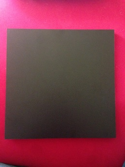
     The real reason for this post being titled "Breaker Breaker" is not because I'm trying to jump in with emergency traffic, or talk to truckers on channel 19 - it's because I just took delivery of a bunch of (6) actual breakers today....
Picture
     Apparently there were a lot arc fault breakers manufactured that were RF sensitive, and they can end up tripping from the RF produced by our Ham radio stations.  For a lot of people this is old news, but for new hams like me, it is new old news, if that makes sense.  The ARRL has a pretty good write up on it here, which includes contact info for whom to call if you have the variety in question, like I do.    
Picture
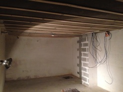
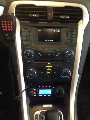
      I noticed the issue quite some time ago, because I was tripping breakers in our recently completed addition while operating "portable" in my back yard with a Buddiepole antenna (I'll have to do a post on this antenna sometime - it's pretty slick).  Since my operations are primarily mobile however, I hadn't gotten around to following up on it.  I finally got around to it though, because while my home shack is under renovation (it still looks like the picture at right) I sometimes operate from my temporary backup station - my desk in the corner of the living room.  I had a picture of it in my very first post, but if you need a refresher, here it is:

Picture
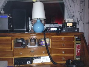
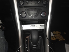
     The station works well considering that the antenna is the downspout and rain gutter, and the ground connection is a piece of steel re-bar (should we take bets on how long it takes to rust out?)  The radio is just my mobile rig that I pull out of the car when I want to operate from the house.  Anyway, while playing radio this winter, a week or so before Winter Field Day, I tripped the breakers and was reminded about the issue.  They even tripped when doing some digital stuff at 20 watts.  The big problem was that the breakers it was tripping included one of the circuits that includes one of our two pellet stoves that heat the house.  If I am forced to choose between playing radio and having a warm house, the YL will let you know in no uncertain terms that having a warm house is more important (I can't argue with that since we have 2 young kids.....)
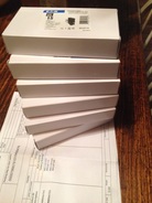
     So, last week I finally got around to e-mailing the two gentlemen listed in the ARRL article, and within a week I had my new breakers, free of charge, sitting on my doorstep.  Now I just have to find time to...  *Ahem*  Now "my certified electrician" has to find time to replace these breakers (all kidding aside - changing breakers isn't a DIY project if you don't know what you are doing - consider yourself warned!) Once that's done, I'll be good as new, playing radio AND being warm!

Previous: Shack Build
Next: Shack Build
0 Comments

New & Improved

2/12/2016

0 Comments

 
     One of the first parts of my mobile shack project that I shared was how I made the panel to fit in the space under the climate controls in my car, to give me a location to mount the control head of my radio.  It looked pretty good, but over time, I started to notice 2 things:
Picture
  1. I fastened the part in place with silicone adhesive. I thought that between the tight friction fit and this adhesive the part would be fairly permanent, but alas, the glue started coming loose, and I noticed some wiggling when I manipulated the radio controls.
  2. The plastic I used to make the part was a cheap cutting board - the material was great, but apparently it doesn't hold paint well, and the paint started to flake off.

Panel  2.0

     The first thing I did was to pop the old part out, and clean all the adhesive off the trim where it had been mounted.  While this was off, my first order of business was to fashion a way to attach the new panel a little more firmly.  
Picture
     I decided to go hard core, and screw something fast.  I had a piece of aluminum bar left over from another project.  I cut it to length, so that I could screw the ends of it to the back of the trim on either side of the panel, and then I would be able to use the metal to attach whatever mounting arrangement I came up with for the panel.  I didn't even bother taking the bar code sticker off, because this would end up hidden behind the new panel part, so in the pictures showing the aluminum bar, you can plainly see the label proclaiming that this is, in fact, the brand of aluminum bar you can get at any of the big box home centers.  Where did we buy our random stuff before Lowes and Home Depot?  Oh wait....the hardware store!  Almost forgot about that place!

Picture
     Once I had this done and screwed in place, I traced the outline of the old panel onto this new piece of plastic, ordered from Tap Plastics.  For the material and size this place was the best price I found in my short search.  It's the same type of material as cutting boards (HDPE) and is marketed for use in marine applications.  I liked it because I knew the material was the type I wanted, and I could order it in black, so I wouldn't have to worry about paint chipping.  As a bonus, I like the texture on this better than the texture on the cutting board that I had used previously.
     After tracing the outline of the old panel, I drilled a hole in the upper left hand corner of the new one, for the bulkhead RJ45 connector.  After having it in the lower left on the first one, I realized that I wanted more wiggle room for my fingers on the buttons on top of the radio, so to shift the radio down, I needed to move the mic jack up.  I also decided that I would use the same screws that attach the radio head to the panel, to attach the panel to the aluminum bar.  This way all the mounting screws would be hidden from view, and I would only need 2 screws to attach both the panel and the radio head.  With this thought in mind, I drilled holes in the new panel for the screws to pass through and hold the remote head mount.  I also drilled a larger hole for the control cable to come through to the back of the radio head.  I then pressure fit the part in place, to use it as my drilling guide to transfer all the same holes to the aluminum.
Picture
     I didn't randomly pick my hole sizes.....I used a drill bit that fit my 10-24 tap, so that the screws that hold the panel and the remote head mount could just thread into this, instead of having to work with nuts, wrenches, etc. in the small tight space behind this location. After doing this, I popped the panel back in place, verified that my holes lined up, and then put the screws in.

Picture
Picture
     After doing this, it was just a simple matter of feeding the control wire through, hooking everything up, and popping the control head back onto it's mount:
​
Picture
     I guess it doesn't look much different than it did in the original pictures, but it looks better than it did yesterday, with the paint flaking off the first part I made.  It also feels a lot more solid - everything is screwed fast, and staying put.
     P.S.  I also drilled another hole and put in another NMO mount recently - I'll fill you in on that part of the project as soon as get to finish it....


di-di-di dah-di-dah
0 Comments

Transformers 2.0

2/4/2016

12 Comments

 
Post contains affiliate links
     After a very cold Winter Field Day, the weather got mild fast, and it rained hard for a day, so our snow is almost gone, and the temperatures are back above freezing.  As promised, this means that I am now revisiting the unun that I recently installed in my vehicle, to do more antenna tuning.  In a previous post I explained the slight lack of clarity in the directions that came with the unit, and talked about my hunch about a better way to go about the process.  
     I basically decided to "start from scratch" so that I could talk you through what I did, what measurements I took, etc.  With that being said here we go.......

Step 1?

     The directions that come with the unit I purchased tell you start by tuning for lowest SWR without the unun in line.  Since I was working with my 40 meter Hamstick, I decided to target the center of the voice portion of the band (I don't plan on doing digital modes and such while driving!)
     The analyzer I have is the RigExpert AA-54, so I exported the charts to my computer after taking my readings - it was my first time playing around with this feature.  I didn't realize how powerful it was!  As I tune the rest of the Hamsticks I might take my laptop along out and use it in the "live" mode.  After tuning for lowest SWR at 7.212 this is what I had:
Picture
    Some interesting notes on this.  The range of the graph covers just slightly more than the 40 meter band.  The SWR at its lowest is 2.05:1 which will work, but isn't great.  The 857d doesn't like SWR levels more than 3:1 per it's manual, so that puts the 3:1 frequency range at 7.138 to 7.282 which is a bit short of covering the whole voice portion available to Extra's.  
     Also, take note of the subset box.  You can see that at the lowest SWR the impedance of the anteanna is 58.5+j38.6.  In my mind this seems like a funny place to start matching from.  My gut (Elmer's jump in if I'm wrong!) tells me that I should be starting from a point where the antenna impedance is pure resistance, i.e. starting from a resonant point, instead of a low SWR point.  I actually had two of these points "relatively" close to the low SWR point.  One of the neat things with loading the data from the analyzer onto the computer is that I can show you those two points on the same graph:
Picture
     The first resonant point, above,  is actually just below the lowest frequency on the scale.  At the very bottom of the scale, we're almost there at 7.7 +j0.2 Ohms.  This would be a 6.48 SWR at resonance.  
     The second resonant point, below, is up at about 7.261MHz (thats as close as the resolution of this graph will show anyway). At that point we've got an impedance of 125.1 +j2.2 ohms for an SWR of 2.5:1 which isn't horrible.  
Picture
    So where should I tune my antenna to, before starting my matching?  

Step 2

     I decided to go with the point where the impedance is 7.7 +j0.2 Ohms, primarily because the unun I bought assumes your antenna side is less than 50 ohms, and matches from there.  It would work the other way just by reversing the input and output, but this means that every time I switch to the 40 meter antenna, I would not only have to change the unun setting, but I would also have to disconnect the coax from both sides, and swap them (or build a switch to accomplish the same thing.)  It seemed easier to just tune to the point where I don't have to re-wire my antenna just to change bands....
     After re-tuning so that resonance was at 7.212 my chart looks like this:
Picture
     From an SWR standpoint - awful, but I'm still hanging my hat on the fact that it's better to start at resonance and then match from there.  This however, is where the directions that come with the unun could leave you wanting.  At this point they say just click through the setting and use the setting with the lowest SWR.  this makes it sound like one of these setting ought to get you close to to 1:1.  This isn't the case.  I ended up re-graphing on each setting, and choosing the setting that had the lowest dip, the closest to 7.212.  This was actually relatively far from where I was.  I had to graph with a really wide frequency range to find the setting with the lowest dip:
Picture
     So after doing these steps, with the unun in line, the lowest SR is 1.13:1, but all the way down at 6.972 MHz.  Time for the final Step.

Step 3

     So, for the final re-tuning of the antenna - re-tuning to get that 1.13:1 SWR point up to 7.212 MHz, which meant shortening the antenna a bit.  After a number of consecutive shortening and re-measuring activities, I ended up here:

Picture
     So after all that, was my thought process sound, and is my final result a good one, or have I unknowingly made this way more complicated than it needed to be, and screwed something up without realizing it?  Hello?  Is anybody out there?
     Oh - on a final note, I re-tuned my 75 meter Hamstick too.  Resonance was very close to low SWR on that one, so the adjustment's weren't nearly as extreme, or as exiting, so I didn't bother sharing the graphs of those.
12 Comments

    Categories

    All
    Antenna
    Cw
    Digital-modes
    Flying-with-gear
    Home QTH
    Miscellaneous
    Mobile
    Operating Events
    Portable
    POTA
    Shack Build
    Technical


    - N3VEM -

         Welcome to my Ham Radio Blog!  This blog was started primarily to share my two concurrent shack builds - my mobile station and my home station.  Over time, this has grown to include sharing about my operations, and general radio-related thoughts that I have as a newer operator.  
         
    ​Enjoy!

    RSS Feed


    Picture
    POTA!

    Picture
    Proving that hams do indeed still build stuff!

    Picture
    100 Watts and Wire is an awesome community, based around an excellent podcast. 

    Archives

    September 2020
    July 2020
    January 2020
    September 2019
    August 2019
    July 2019
    June 2019
    May 2019
    March 2019
    January 2019
    December 2018
    November 2018
    October 2018
    September 2018
    August 2018
    July 2018
    June 2018
    May 2018
    April 2018
    March 2018
    February 2018
    January 2018
    December 2017
    November 2017
    October 2017
    September 2017
    August 2017
    July 2017
    June 2017
    May 2017
    April 2017
    March 2017
    February 2017
    January 2017
    December 2016
    November 2016
    October 2016
    September 2016
    August 2016
    July 2016
    June 2016
    May 2016
    April 2016
    March 2016
    February 2016
    January 2016
    December 2015
    November 2015


Picture
Copyright © 2015
 Vance Martin is a participant in the Amazon Services LLC Associates Program, an affiliate advertising program designed to provide a means for sites to earn advertising fees by advertising and linking to amazon.com.