NOVEMBER 3 VICTOR ECHO MIKE
  • Blog
  • Events and Activations
  • Diversions
  • About
  • Gallery
  • Contact
  • Links
  • Subscribe
  • Search
  • Blog
  • Events and Activations
  • Diversions
  • About
  • Gallery
  • Contact
  • Links
  • Subscribe
  • Search
NOVEMBER 3 VICTOR ECHO MIKE

ham radio Projects and musings from a (Relatively) new operator

Transformers 2.0

2/4/2016

12 Comments

 
Post contains affiliate links
     After a very cold Winter Field Day, the weather got mild fast, and it rained hard for a day, so our snow is almost gone, and the temperatures are back above freezing.  As promised, this means that I am now revisiting the unun that I recently installed in my vehicle, to do more antenna tuning.  In a previous post I explained the slight lack of clarity in the directions that came with the unit, and talked about my hunch about a better way to go about the process.  
     I basically decided to "start from scratch" so that I could talk you through what I did, what measurements I took, etc.  With that being said here we go.......

Step 1?

     The directions that come with the unit I purchased tell you start by tuning for lowest SWR without the unun in line.  Since I was working with my 40 meter Hamstick, I decided to target the center of the voice portion of the band (I don't plan on doing digital modes and such while driving!)
     The analyzer I have is the RigExpert AA-54, so I exported the charts to my computer after taking my readings - it was my first time playing around with this feature.  I didn't realize how powerful it was!  As I tune the rest of the Hamsticks I might take my laptop along out and use it in the "live" mode.  After tuning for lowest SWR at 7.212 this is what I had:
Picture
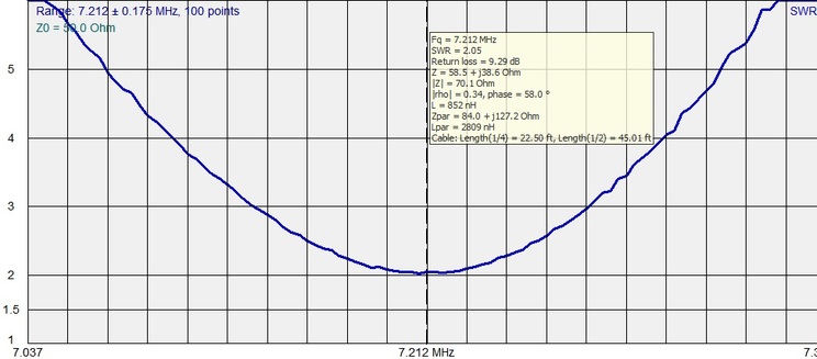
    Some interesting notes on this.  The range of the graph covers just slightly more than the 40 meter band.  The SWR at its lowest is 2.05:1 which will work, but isn't great.  The 857d doesn't like SWR levels more than 3:1 per it's manual, so that puts the 3:1 frequency range at 7.138 to 7.282 which is a bit short of covering the whole voice portion available to Extra's.  
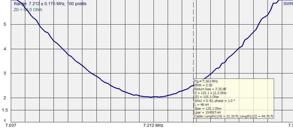
     Also, take note of the subset box.  You can see that at the lowest SWR the impedance of the anteanna is 58.5+j38.6.  In my mind this seems like a funny place to start matching from.  My gut (Elmer's jump in if I'm wrong!) tells me that I should be starting from a point where the antenna impedance is pure resistance, i.e. starting from a resonant point, instead of a low SWR point.  I actually had two of these points "relatively" close to the low SWR point.  One of the neat things with loading the data from the analyzer onto the computer is that I can show you those two points on the same graph:
Picture
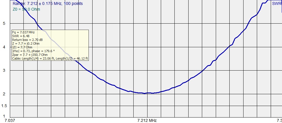
     The first resonant point, above,  is actually just below the lowest frequency on the scale.  At the very bottom of the scale, we're almost there at 7.7 +j0.2 Ohms.  This would be a 6.48 SWR at resonance.  
     The second resonant point, below, is up at about 7.261MHz (thats as close as the resolution of this graph will show anyway). At that point we've got an impedance of 125.1 +j2.2 ohms for an SWR of 2.5:1 which isn't horrible.  
Picture
    So where should I tune my antenna to, before starting my matching?  

Step 2

     I decided to go with the point where the impedance is 7.7 +j0.2 Ohms, primarily because the unun I bought assumes your antenna side is less than 50 ohms, and matches from there.  It would work the other way just by reversing the input and output, but this means that every time I switch to the 40 meter antenna, I would not only have to change the unun setting, but I would also have to disconnect the coax from both sides, and swap them (or build a switch to accomplish the same thing.)  It seemed easier to just tune to the point where I don't have to re-wire my antenna just to change bands....
     After re-tuning so that resonance was at 7.212 my chart looks like this:
Picture
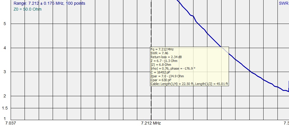
     From an SWR standpoint - awful, but I'm still hanging my hat on the fact that it's better to start at resonance and then match from there.  This however, is where the directions that come with the unun could leave you wanting.  At this point they say just click through the setting and use the setting with the lowest SWR.  this makes it sound like one of these setting ought to get you close to to 1:1.  This isn't the case.  I ended up re-graphing on each setting, and choosing the setting that had the lowest dip, the closest to 7.212.  This was actually relatively far from where I was.  I had to graph with a really wide frequency range to find the setting with the lowest dip:
Picture
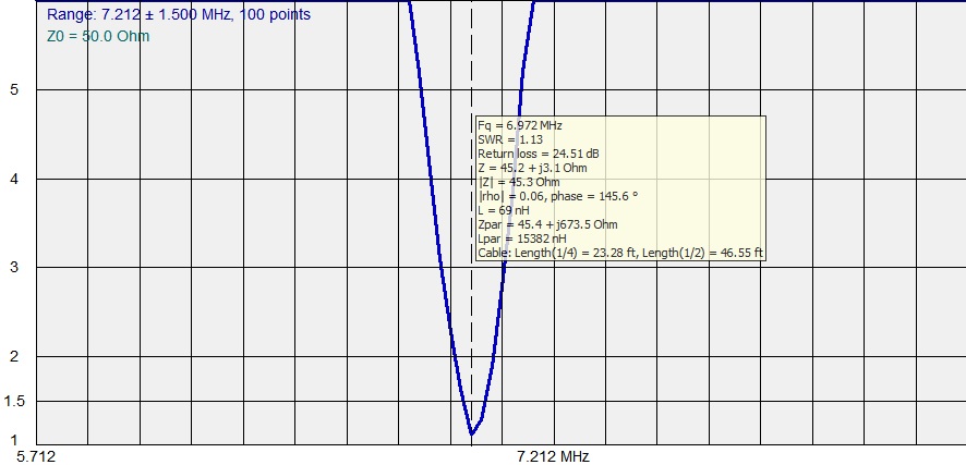
     So after doing these steps, with the unun in line, the lowest SR is 1.13:1, but all the way down at 6.972 MHz.  Time for the final Step.

Step 3

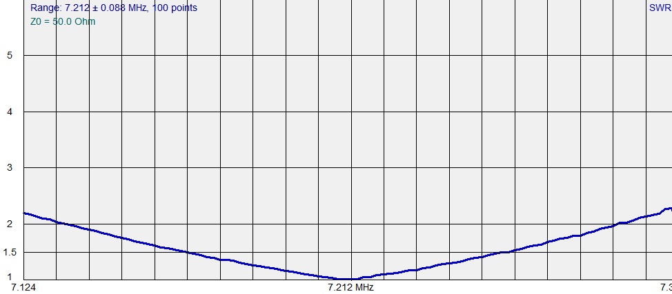
     So, for the final re-tuning of the antenna - re-tuning to get that 1.13:1 SWR point up to 7.212 MHz, which meant shortening the antenna a bit.  After a number of consecutive shortening and re-measuring activities, I ended up here:

Picture
     So after all that, was my thought process sound, and is my final result a good one, or have I unknowingly made this way more complicated than it needed to be, and screwed something up without realizing it?  Hello?  Is anybody out there?
     Oh - on a final note, I re-tuned my 75 meter Hamstick too.  Resonance was very close to low SWR on that one, so the adjustment's weren't nearly as extreme, or as exiting, so I didn't bother sharing the graphs of those.
12 Comments
Jeff
3/3/2016 12:23:16

What equipment exactly is it that you are referring to as an " UN-UN "?

In my book, this is a transformer, but you say that yours has 'settings' on it? Are you not talking about an ANTENNA TUNER?

If the instructions say to start from the lowest SWR setting, then start from the lowest SWR setting.

Don't second guess, because that would be wrong in this case.

Reply
Jeff WR2E
3/3/2016 13:09:57

OK, I see now that you have one of those multi-tap MFJ transformers that allows you to change impedance ratios, so you can disregard the question about the " un-un ".

I wonder what's really inside that box?

Reply
Vance - N3VEM
3/3/2016 13:20:19

Jeff - you've got it - I'm using the MFJ un-un, which (based on the schematic I found somewhere on the internet) is really a basic transformer, it just has several different taps on the inductor connected to a rotary switch so you can pick between values. I didn't explore building one on my own, because according to K0BG's website, buying the pre-made one from MFJ is just as inexpensive as buying the parts to build one yourself. Since you asked though, now I think I might take the unit apart when I have time just to verify that is what is going on inside the "magic box."
Thanks for you input, and let me know if that changes anything in the thought process for tuning up. The main reason I went with starting from resonance instead of low SWR is because of of one of K0BG's articles, where he describes a similar process when hand winding an inductor for use with mobile antenna's, and tuning based on that.

Reply
Jeff WR2E
3/3/2016 13:27:13

I just looked at what you have there... it's a box with a bunch of capacitors in it.

I still would say to follow the instructions to start by tuning the antenna to the lowest SWR and then inserting the switched capacitor box and readjusting that box for lowest SWR.

The capacitor box is actually forming an L-network antenna tuner using the inductance of the antenna as half of the "L".

In a mobile environment, you are basically most concerned with what the rig sees. You want it to be at it's happiest place with the lowest SWR on the output.

Reply
Vance - N3VEM
3/3/2016 13:34:24

Jeff - Thanks for the feedback! I'll try the process from scratch again, doing it that way, and see how it looks. I'll probably do a follow up post with the readings I get doing it that way for comparison.

Jeff WR2E
3/3/2016 17:48:32

I told ya wrong Vance. I took a closer look at the matching box that you have and see that what I thought was a "9" is a "7", so you've got the MFJ-907, not the MFJ-909!

And it IS an impedance transformer.

Shouldn't change anything though, you still want to start with the antenna itself tuned to it's lowest SWR setting, and then transform that impedance using the transformer.

Reply
Hal WA1ZJL
3/4/2016 19:05:53

Hi Vance
You are correct in starting from resonance with your antenna matching procedure. Most vertical antennas have an extremely low impedance at resonance if all the technical manuals are to believed. You have shown this to be correct with your measurements. I believe that antennas radiate most efficiently at their resonance point. There is a website with lots of good information. It is www.k0bg.com. I ran across this site after reading an article in QST on a 17 meter mobile antenna project written by a VE. All of the technical information from both of these gentlemen appears sound and I was a broadcast engineer for most of my career so I think I can sort out the fact from fiction. Good luck with your mobiling and maybe I'll get a mobile station up and running one of these days and work you!
73

Reply
Jeff WR2E
3/4/2016 23:31:52

I have to disagree Hal.

Any extra 'efficiency' that might be gained by having the antenna at 'resonance' is going to be far outweighed by the loss in the coax cable running at an swr of 6 or 7 to one.

If Vance's matching device is at the transmitter and then there's ten feet of coax between it and the antenna the loss in that cable will be far more than any imaginary efficiency gain by resonating the antenna.

An off resonance antenna will radiate just fine as long as the RF energy can be coupled to it. It's far more important to minimize losses by minimizing swr and getting the most power to the antenna as possible than it is to run the antenna at resonance.

Reply
Vance - N3VEM
3/4/2016 23:40:58

I love a good debate! In case it makes any difference, for clarification, my marching device is at the base of the antenna, so I don't think I need to worry about coax loss - in a mobile environment, I don't know that there is ever enough coax to make a significant amount of loss anyway, unless the SWR is crazy high.

Jeff WR2E
3/5/2016 09:11:55

Yes, it does make a difference!

At the antenna is the ideal spot for a matching device.

In this case it may not make much difference at all where you start from!

Let's face reality... A mobile antenna is going to radiate equally poorly in all directions no matter what you do, resonant or not. Your job then is to experiment and find what works best, theory be damned.

Measuring 'efficiency' will require the use of a field strength meter. It can't be done by ear, with an swr meter, or by on the air signal reports.

Proper field strength measurements are not terribly easy to do! Yes, taking measurements is easy. But relating them to one antenna configuration being 'better' than another requires careful setup, an IDENTICAL set of conditions between setups, etc

The single best thing that you can do to improve mobile setups is to REDUCE GROUND LOSSES by mounting the antenna to the vehicle in the best way possible.

Where and how do you have the antenna mounted on the car has way way way more to do with radiation efficiency than anything else.

Jeff WR2E
3/5/2016 11:14:55

Hi Vance, In re-reading your original post, I've got a question, maybe two.

In the last chart with what looks like an awesome match, did you then go back and re-chart the antenna without the matchbox to see what that looked like? Might be interesting.

Are you connecting the analyzer at the antenna feed point, or at the end of the feedline. I'm sure you know that feedline will transform impedance measurements.

In fact, take a look at my QRZ page for the HF antenna I'm using here at home. I'm actually using different length feedlines to match my 80 meter doublet on all bands. Thanks to Cecil, W5DXP for the awesome idea!

Reply
Vance - N3VEM
3/5/2016 15:02:41

Jeff - I haven't re-measured with the matchbox out of line - I might do that today thought if I can sneak off after the kids go to bed tonight, because it would be interesting to see the difference.
As far as where I took the readings - all the readings I took without the matchbox in line I took pretty much right at the base of the antenna, where the matchbox would connect - only a few feet of coax. The readings with the matchbox in line, I initially took right from the "transceiver side" of the matchbox, and then once everything was all set, I took another reading from the end of the coax right at the transmitter to see if the extra length of feedline between the matchbox and transceiver would have any effect. On the bands that I have taken measurements on it doesn't, so I must have a length that is pretty much non-resonant.
I did take a peek at your QRZ page, so I know that if I have questions about doing stub transformation with lengths of feedline, you're the guy to go to! That's a pretty slick relay/switching arrangement you have rigged up!

Reply

Your comment will be posted after it is approved.


Leave a Reply.

    Categories

    All
    Antenna
    Cw
    Digital-modes
    Flying-with-gear
    Home QTH
    Miscellaneous
    Mobile
    Operating Events
    Portable
    POTA
    Shack Build
    Technical


    - N3VEM -

         Welcome to my Ham Radio Blog!  This blog was started primarily to share my two concurrent shack builds - my mobile station and my home station.  Over time, this has grown to include sharing about my operations, and general radio-related thoughts that I have as a newer operator.  
         
    ​Enjoy!

    RSS Feed


    Picture
    POTA!

    Picture
    Proving that hams do indeed still build stuff!

    Picture
    100 Watts and Wire is an awesome community, based around an excellent podcast. 

    Archives

    September 2020
    July 2020
    January 2020
    September 2019
    August 2019
    July 2019
    June 2019
    May 2019
    March 2019
    January 2019
    December 2018
    November 2018
    October 2018
    September 2018
    August 2018
    July 2018
    June 2018
    May 2018
    April 2018
    March 2018
    February 2018
    January 2018
    December 2017
    November 2017
    October 2017
    September 2017
    August 2017
    July 2017
    June 2017
    May 2017
    April 2017
    March 2017
    February 2017
    January 2017
    December 2016
    November 2016
    October 2016
    September 2016
    August 2016
    July 2016
    June 2016
    May 2016
    April 2016
    March 2016
    February 2016
    January 2016
    December 2015
    November 2015


Picture
Copyright © 2015
 Vance Martin is a participant in the Amazon Services LLC Associates Program, an affiliate advertising program designed to provide a means for sites to earn advertising fees by advertising and linking to amazon.com.