Post contains affiliate links
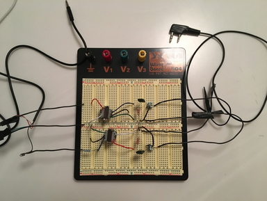
For several weeks now I've been slowly working away at a mini-project, building a sound interface to use with my iPhone and tablet for digital modes. If you're just joining me, you can go back and start with part 1, when the project looked like this:
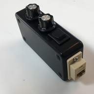
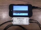
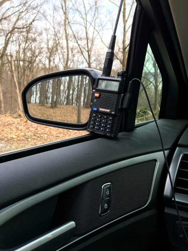
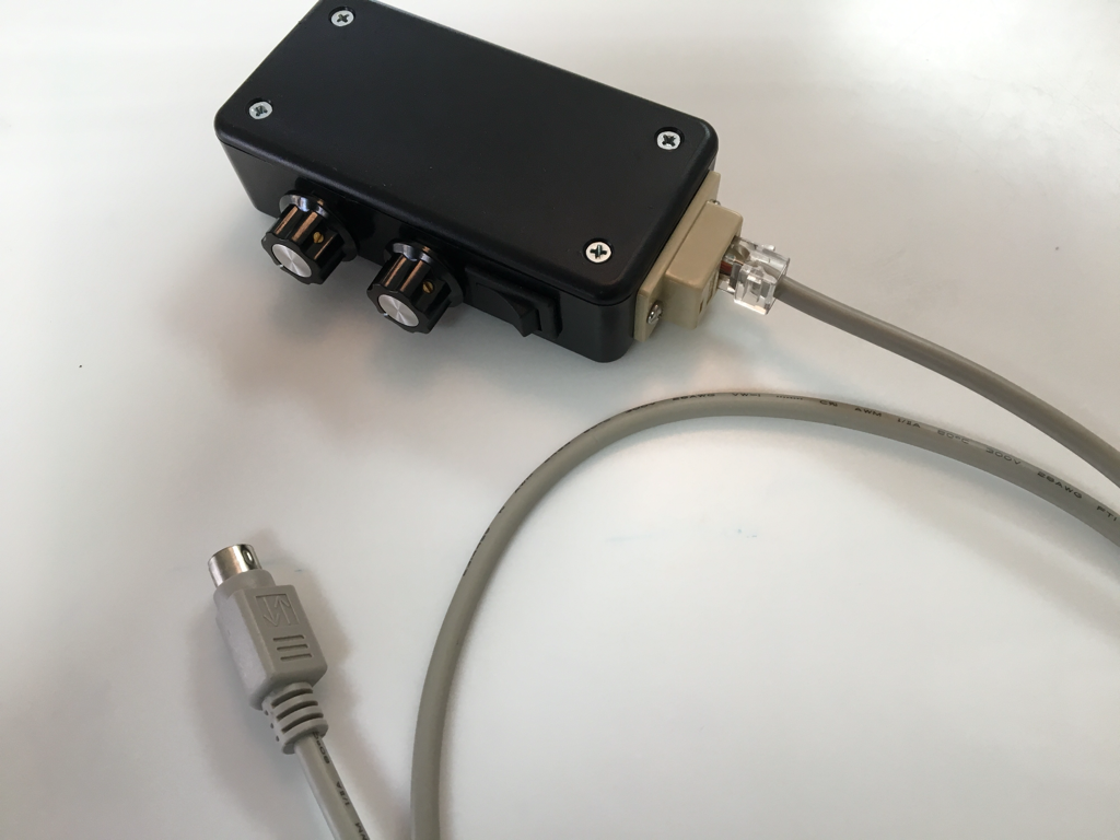
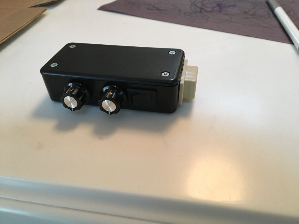
To find out what happened between then and now, read on, and I'll share with you how it got from what you see above, to this:
|
|
|
Now, before I get too far, I have to share the fact that if you don't have the patience to "roll your own" you can buy something very similar to this, either complete or in kit form on eBay. There are a couple different versions though, so make sure you get the one that fits your application! There are models available for iPhone connection, PC connection, different radios, PTT triggered, VOX triggered, etc. Each one of these is the same basic circuit, but with slight tweaks for each application.
|
Easy Digi for iPhone - available on eBay
Easy Digi for iPhone and Baofeng
Easy Digi PC soundcard Interface Kit
|
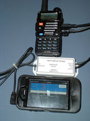
When I last left you, I had the interface working, and had already verified that the audio was working in both directions, using one of the world famous Baofeng UV5R radios. With the basic circuit working, I was ready to start thinking about a proper enclosure, and proper cables for connecting my phone and radios.
|
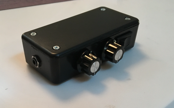
The connection for the phone was easy - since modern smart phones and tablets use 3.5mm TRRS (4 conductor audio) cables, I ordered a TRRS jack that I planned on putting in one end of whatever enclosure I ended up getting. This would let me connect my phone to the device with any 3.5mm TRRS male to male cable.
|

Clickable Amazon Links!
 |
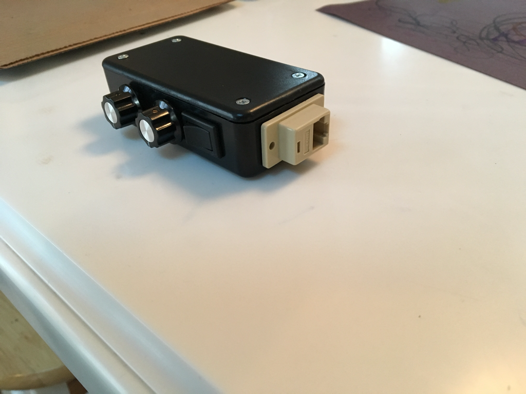
The "other" end was something that I debated over. Because I wanted to use this with a couple different types of radios I knew I wanted some type of modular plug so that I could make up at least 2 different cables - one for my HT and one for my Yeasu 857d.
My first thought was to use an RJ12 jack. These jacks are the same size as the traditional RJ11 jacks used for old-school telephones (does anyone still use house phones?). The main difference is that RJ12 jacks and plugs use all 6 connection points, instead of just the middle 4. When it came time to acquire the part however, this isn't what I ended up getting. I was clicking around a bunch of different sites, trying to decide where to place my order, and in my late-night clicking stupor I ended up ordering an RJ45 jack instead - as it turns out I'm glad I did!
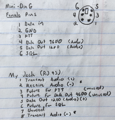
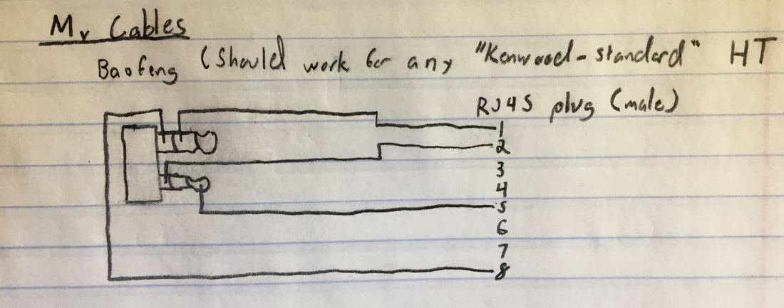
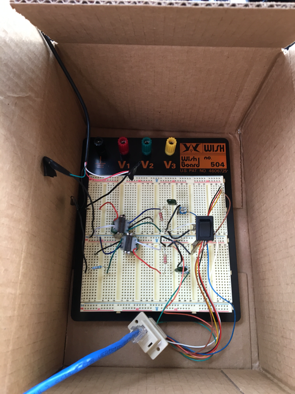
The order with my RJ45 jack came first, so I wired it up to the "radio" side of the circuit on my breadboard. To make things tidy, and easy for me to follow I looked up the standard pin numbering for RJ45 plugs. Since I would also be making a cable to connect to the data port on my rig (which uses the standard mini-din 6 format) I also looked up the standard pin numbers for the mini-din format. This way I was able to make the connections on my circuit so that when I was ready to make cables, pin 1 for the radio would equate to pin 1 on my interface, pin 2 to pin 2, up through pin 6.
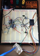
As some of you may have noticed, I draw pictures in a notebook when I work on things - doing this helps to cement the concepts of whatever I'm working on into my head. With that thought, here are my notes from working out the pins, and a picture of the jack wired to the breadboard when I was playing around with it:
As some of you may have noticed, I draw pictures in a notebook when I work on things - doing this helps to cement the concepts of whatever I'm working on into my head. With that thought, here are my notes from working out the pins, and a picture of the jack wired to the breadboard when I was playing around with it:
|
|
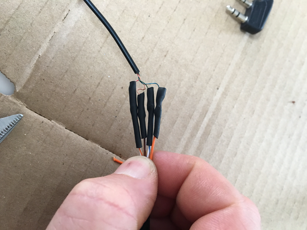
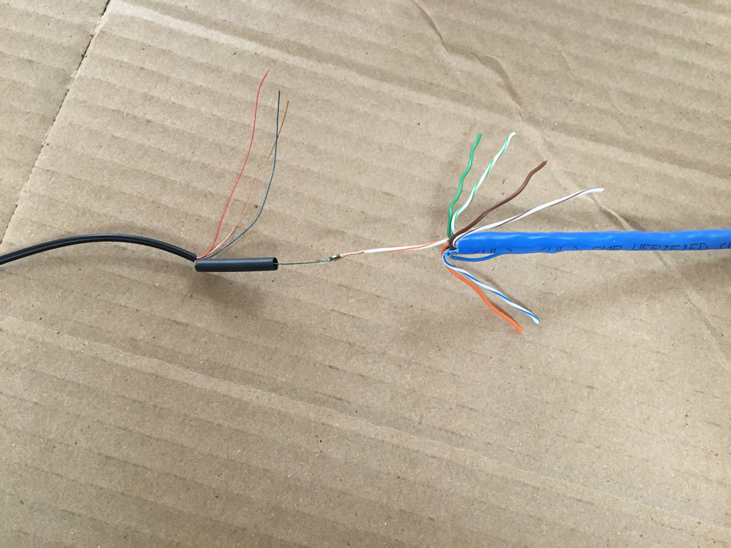
At this point I was still waiting for a couple of parts from another vendor. In the interest of working with what I had on hand, I next made up a cable for my Baofeng HT. The actual wires in the HT plug I was using were too small to fit directly in the RJ45 plug (remember those TINY enamel coated wires I talked about?!) Since they were too small I spliced them together with solder and heat-shrink onto a short section of Cat5e cable. I then put a large piece of heat shrink over the entire group of individually spliced wires, and then put the RJ45 plug onto the other end of that, being careful to make sure my wires lined up with the pin-out I referenced above.
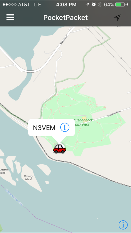
With the new cable made up, and me still waiting on some of the other little parts to arrive, I decided to do another "test" to make sure I didn't accidentally undo any of my previous work, and to make sure that my new modular jack was wired correctly. For this test I put the temporary circuit into a temporary enclosure (aka, a cardboard box) and took it along on a family drive to our closest state park (Susquehanock - I'll probably be doing a WWFF activation here soon.) I successfully sent out a couple packets via APRS so I know the cables and jack were wired up correctly!
Now, at this point the most observant among you might be saying, "Hey, I see a switch in the circuit on your breadboard in some of those pictures...you never mentioned a switch!" To you I say, "good catch!"
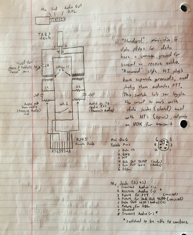
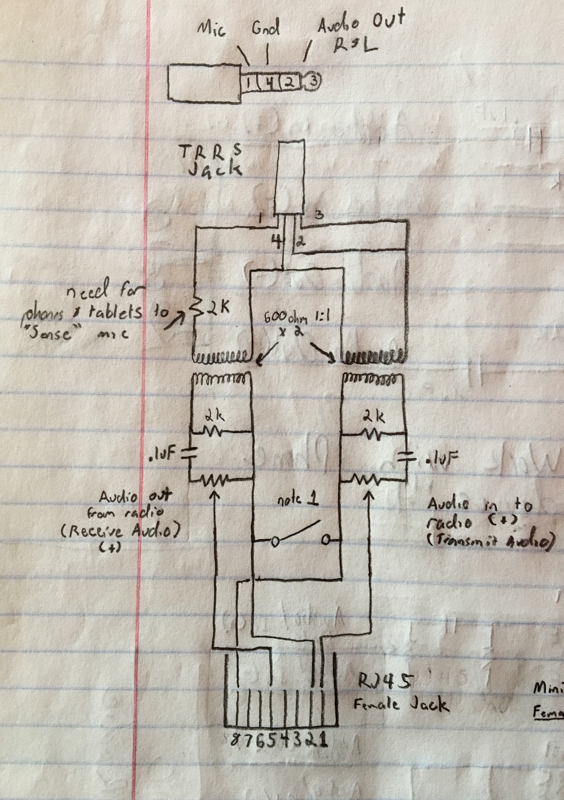
Something I realized while I was working on this is that on the "radio" side of the circuit the mini-din connectors only have 1 ground connection that is shared for all of the other connections, while the Baofeng or Kenwood style HT plugs need separate grounds for transmit and receive audio. This is because on these radios, connecting the two grounds together is what activates the PTT. The switch gives me a way to use the same devices for both radio types. With the switch wired between the 2 grounds, leaving the switch in the open position lets it work with HT radios (using VOX), and putting the switch in the closed position makes it work with standard mini-din data ports (also using VOX.) With all these little discoveries, I'm finally ready to share my "final" schematic for this circuit....
Behold! The AnnaLink schematic as it appears in my notebook:
|
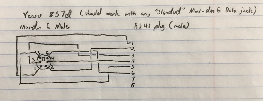
Shortly after this, my mini-din 6-pin cable arrived. I ordered one that was 6 feet, and male to male, so that I could cut it in half and make up 2 cables. Wiring it up when it came was pretty simple because of my care to make sure the pin numbers would match up in a 1 to 1 relationship:
|
 |
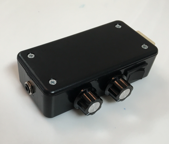
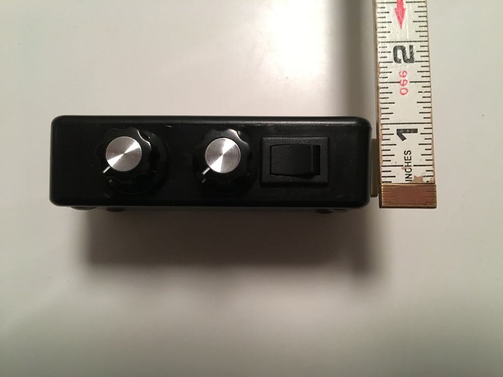
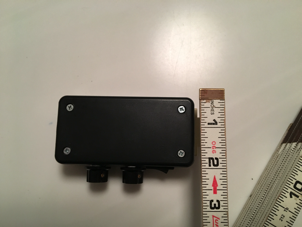
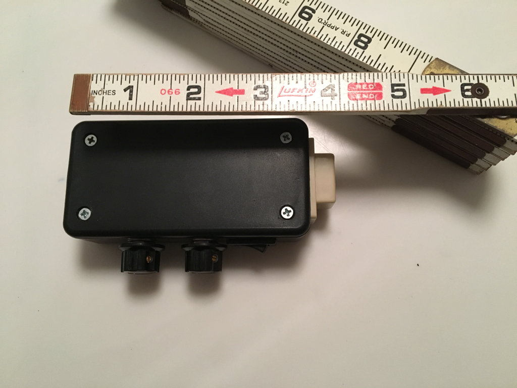
Next, it was time to finally put this in an enclosure. I made a trip to the local Radio Shack (stuff is on clearance since they're apparently closing another round of stores and filing bankruptcy-again...) and picked up the smallest project box I thought I could fit everything in. At this point I also picked up 2 different potentiometers because I wanted something I could mount in the box, and put knobs on. I ended up getting audio taper potentiometers instead of linear, because the rate at which they change the level (logarithmic) is supposed to feel more natural for audio applications.

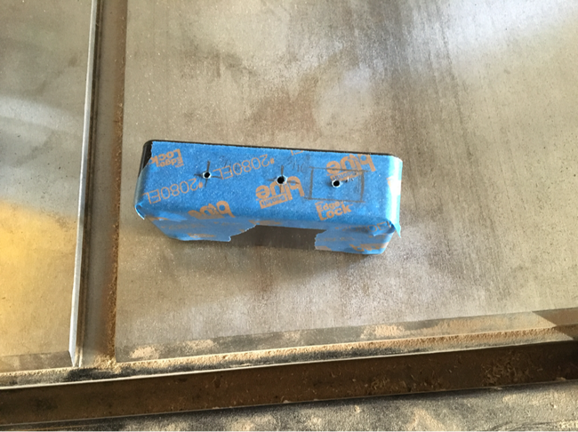
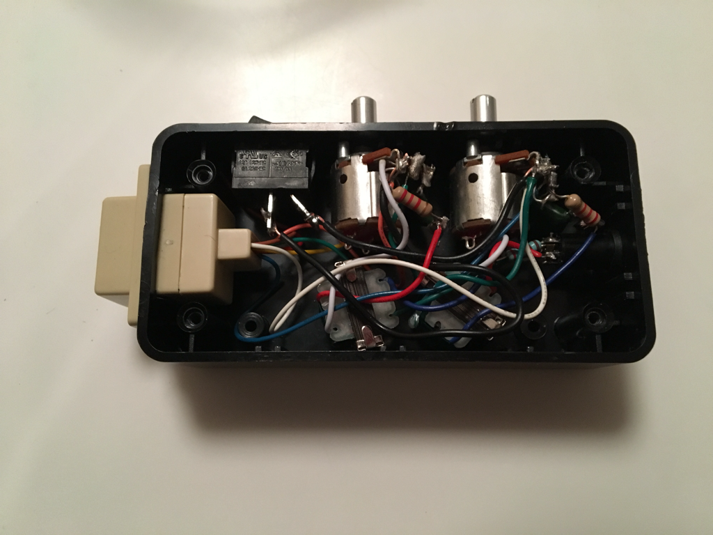
Once I had these in hand, I also decided at that point that I would just mount everything in the box and do point to point wiring, because the number of components is small, and I could rely on the potentiometers to be the physical strength, and simply attach the smaller components directly to them. The pictures below show my markup method for making the holes, and the final product:
|
|
|
|
|
|
|
|
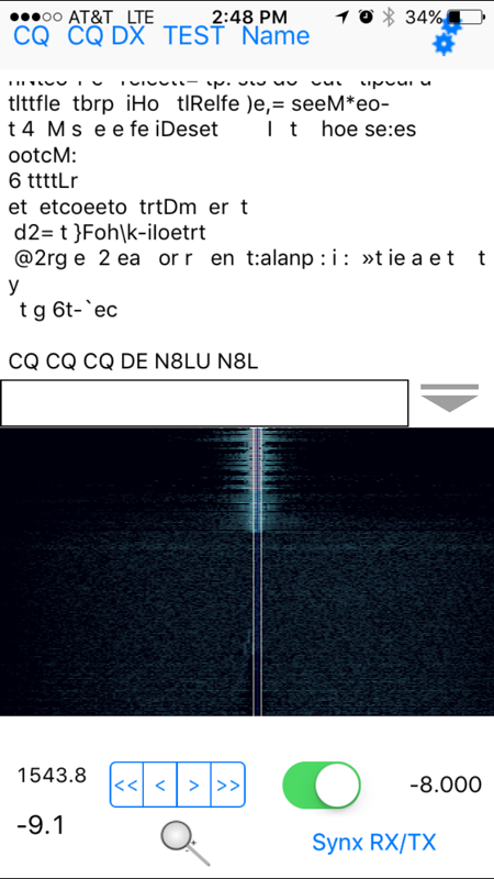
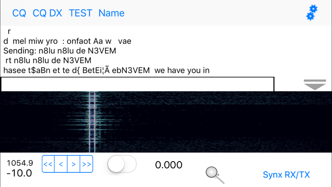
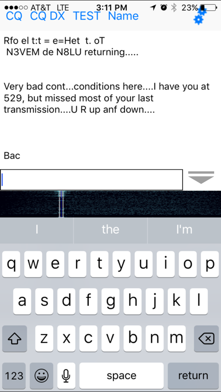
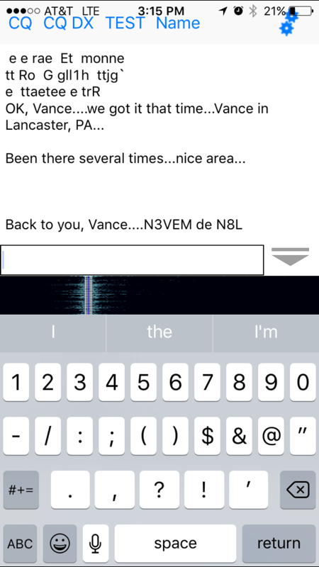
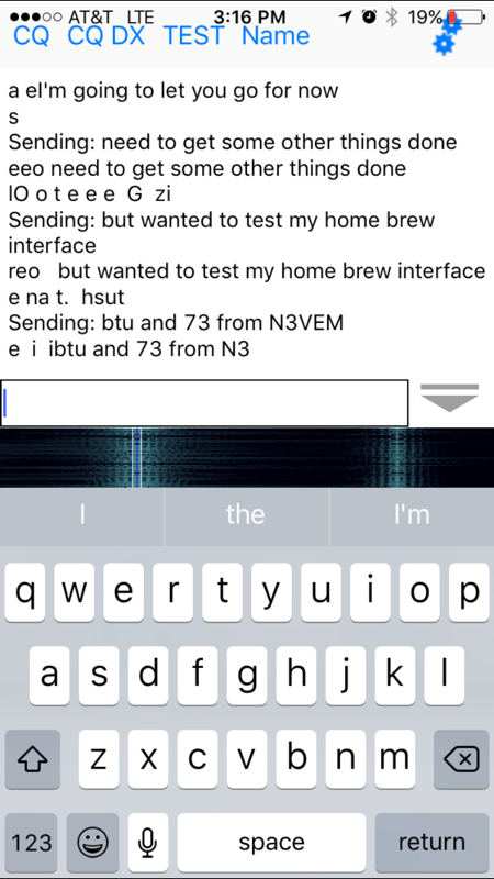
For those of you who were patient enough to hang in there through all of this, here's some proof that it all worked! A contact with N8LU using 5 watts from my 857d, and the PSKer app on my iPhone. This app has mixed reviews, and I'll share my own full review at some point, but as far as I can tell it's the only iPhone app that will both send and receive PSK31 using the phone as an audio modem, so despite its shortfalls, it's the best (only?) one out there for iPhones (there are more options if you're an Android person.)
With that, this looong post is finally over! Thanks for sticking around, and feel free to ask me questions or leave comments - especially if you plan on building your own!
 RSS Feed