Post Contains Affiliate Links
Welcome to my promised follow up about the sound card interface that I've been playing around with! If you didn't read about my initial attempts at making a basic interface to connect my iPhone and Tablet to my rig, check out Part 1 here!
In case you're curious, this post is called AnnaLink because that is now the official name of this little project. My daughter "helped" me put this together - which really consisted of me explaining a schematic, and her just nodding, and asking when she could poke parts into the breadboard....apparently that was the fun part :-) Anyway, as she was having fun poking resistors and things into the little holes, she asked me "Daddy, what are we going to call it?" I told her it should have "link" in the name because of what it does, and AnnaLink is what she decided, so AnnaLink it is.... If you read part 1 of this little project, you know that I actaully already had this mostly put together. If you happen to follow me on Instagram or Twitter:
you also got a sneak peek at my test drive where I put the whole thing on the dashboard of my car, and drove down the road to fire off a few APRS packets using my iPhone and HT. (Psst....I sometimes throw random pictures of stuff up on Twitter and Instagram before I write my posts, but don't tell - it's a secret...)
So what was I working on? Well, between my last post on this project and my test drive, I learned a couple things about the circuit I put together. I had also promised a couple sketches of the circuit in case anyone wanted to play along. With that in mind, I started this evening by sketching out the circuit, tearing the circuit apart, and then putting it all back together following the sketch. I did all that so that I could double check my own work. Here's how it went:
So what was I working on? Well, between my last post on this project and my test drive, I learned a couple things about the circuit I put together. I had also promised a couple sketches of the circuit in case anyone wanted to play along. With that in mind, I started this evening by sketching out the circuit, tearing the circuit apart, and then putting it all back together following the sketch. I did all that so that I could double check my own work. Here's how it went:
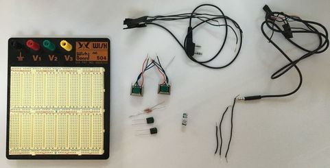
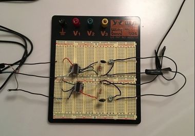
The first thing I did, was to pull everything back off the bread-board and lay it out. When you look at it this way, it's obvious that this is a very basic circuit, because there aren't really that many parts:
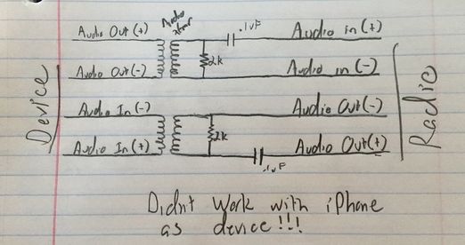
And since we're starting from the beginning, I'll start by showing you the schematic that I first found online. There are piles of this exact same diagram that pop up when you do a Google search for "Soundcard Interface", but they all follow this basic layout (P.S. I am not an Electronics Professional - just a hobbyist, so if my diagram doesn't show something "correct" and you are offended, feel free to comment and let me know, that's how we all learn! If you're nasty about it though, I'll just ignore you...)
If you'll recall from my prior post, I mentioned that I tested, and verified, that the audio from my iPhone traversed this circuit just fine. The catch however, that I found prior to my test-drive, was that it didn't seem to be working the other way around - audio wouldn't get back into my iPhone through the mic connector. After a lot of grumbling, poking at stuff with my multi-meter, and lots of Googling, I found out what I was missing, in the corner of some internet forum (can't remember which one - sorry!) What I found was something that was new to me, and might be new to anyone that hasn't had much experience with modern smart-phones and tablets:
Older devices and larger devices use a mic jack that has extra contacts in it, that act as a mechanical switch to sense when something is plugged in. Newer devices, and devices that have a small footprint no longer do this mechanically - they do it electrically. The mic connector actually provides a bias voltage that needs to pass through a resistor in the device being plugged in, before it will recognize that something is plugged into the mic port. On the iPhone, if you have a direct short between the mic (sleeve on the TRRS connector) and ground (one of the Rings on the TRRS connector) it ignores the mic, because this is exactly what happens when you plug in normal headphones (that don't have a mic.) By design, this is good for most users, because it lets them listen to the iPhone on traditional headphones, but use the microphone on the phone to talk, if needed.
For the circuit I made, this meant that my iPhone was ignoring the mic, and trying to use the built in speaker-mic because there is a direct DC path between Mic and Ground!
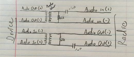
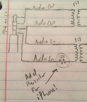
Luckily, once I was finally enlightened to how the mic sensing worked, the fix was pretty simple - stick a 2k resistor in the path for the microphone! As a note, in my drawing below, at this point I also sketched in the two potentiometers that I added so that levels passing through the device could be adjusted. Putting them in the circuit this way just makes a voltage divider. If you're very new to electronics the website All About Circuits has a lot of useful information, projects, and even a free textbook series, if you're not sure what I mean by voltage divider.
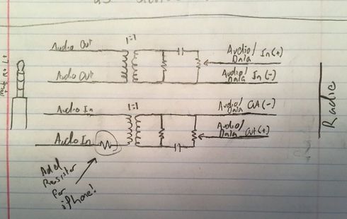
Of course after I went through all this, I happened to stumble on an interface for sale on ebay, advertised to work with the iPhone. Looking at the circuit on that device (a schematic was included with the pictures!) I could see that the needed resistor was included in their design. Why couldn't that have been the schematic I found first?! Oh well - this way I know why the resistor is there, and can share that info, rather than just saying that it's there because the picture told me to put it there :-)
To connect this to my phone I grabbed a headset extension cable, and just cut off the end I needed, along with a a foot or so of cable. If you happen to have an old headset lying around that doesn't work, repurpose that cord! The connections to the plug can be sounded-out with your meter, but on mine the wires went like this:
- Left Audio Out - White
- Right Audio Out - Red
- Ground - Green
- Mic - Black
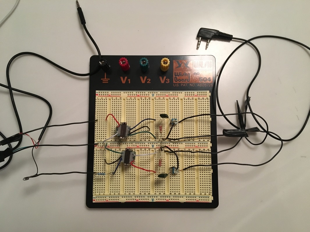
So, enough of my bad scribbles, here's a picture of the real deal, on a breadboard, after my daughter did the fun part of poking the parts into the right holes:
I had an earpiece from a Baofeng radio that was junked but the plug and cable were still good, so I scavenged that to make up a connector. Here's another tip - this is something I never knew because I never worked with wire this small before..when you strip the outer jacket, the individual conductors in these ear pieces are TINY. They way they are made is that each individual "hair" in each bundle is coated in enamel, so you can't really strip the wires. Essentially, you treat them like you would a bare wire - tin the ends, and then solder them - the heat in that process melts away the enamel and then the wires can make contact. This might be old news to folks who have worked with small wire and magnet wire, but it was new to me!
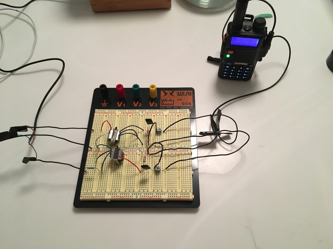
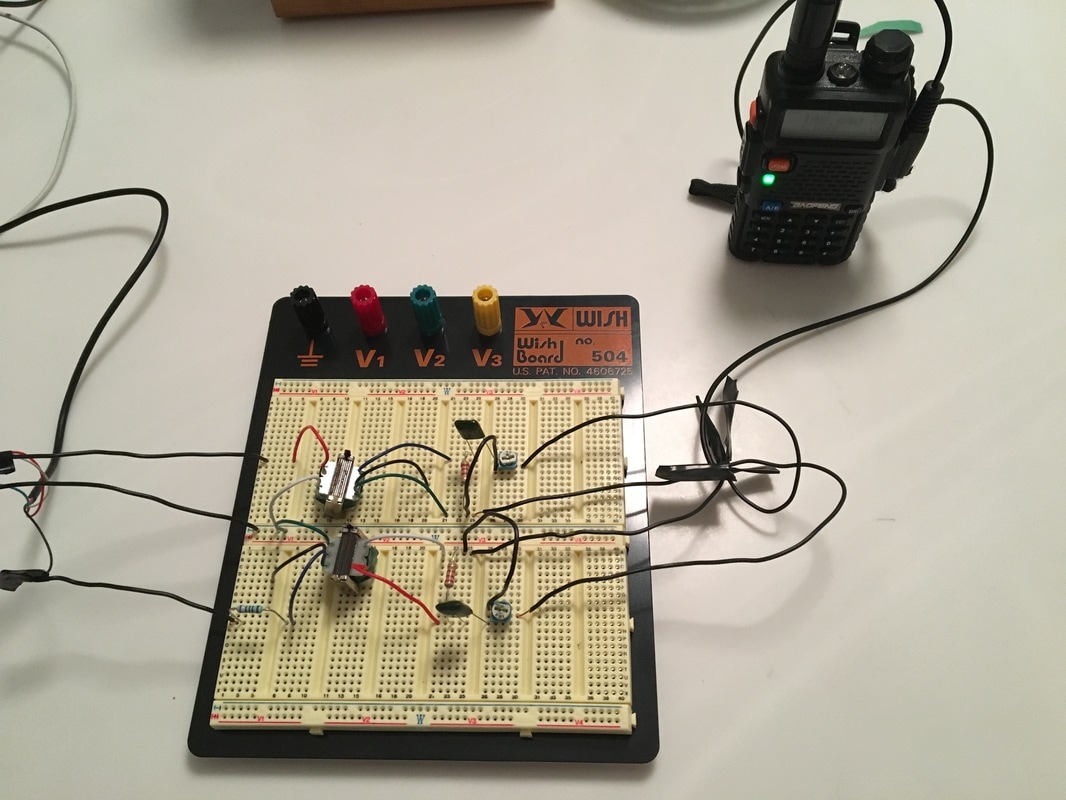
Doing the above allowed me to verify that this would work for anything with the Kenwood "style" of plugs. I verified the receive audio portion by tuning to a local repeater and recording the conversation that I heard using the "Voice Memo" app on my phone. I then verified that the transmit audio portion was working by taking the drive I mentioned at the beginning of this post - I used APRS.fi to make sure my packets got out - worked great!
If you want to mimic the same thing, the connections on this style of plug are pretty straight-forward as well, and are also spelled out in many places online....here's my low-tech version of that diagram:
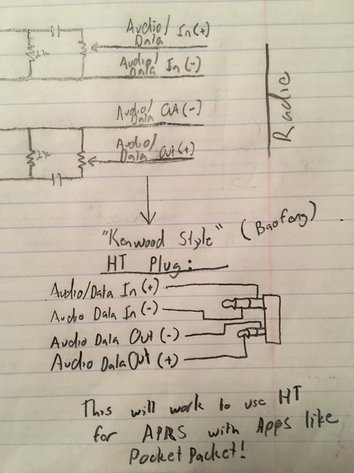
Here's a couple of shots of the plug wired up, and the receive portion in action. I couldn't get a shot of the transmit because APRS packets burst out so fast that the transmission ended by the time I could get my phone to take the picture - after a couple attempts to catch that in a photo I gave up :-)
Whats next for this little mini-project?
- Order a connector so I can wire something up to connect to my Yeasu 857d
- I grabbed an old keyboard at a thrift shop for this because it had the right connector (PS/2 = Mini Din-6), and was cheaper then buying and shipping the actual connector, but it turned out the connector on the keyboard wasn't actaully using all the pins, and a couple of the missings pins were ones specifically needed to connect to the data jack on the 857d.
- Test it out using my 857d and make some PSK and SSTV contacts
- Build the circuit in a more permanent way
- Call it done!
Are you interested in playing along? Below is the stuff you will need, with clickable Amazon links. If you look around you can probably find these same items cheaper by getting exactly the quantity you need, but with these types of things it never hurts to have spares for your project stash. Many of these things are small, so for a small amount of money you can have everything you need to replicate what I did, AND have a bunch of stuff left over for your project box!
 |
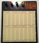
Breadboard and Jumpers together in one package! This type of arrangement is the basis for a lot of my experimentation with small circuits.
|
 |
Audio Transformers. In ham radio these are great to have around because they can be used in quite a few sound applications where you need to isolate devices from each other!
|
 |
2k Resistors. You might already have a stash of these, but if not, start your stash now!
|
 |
.1 uF Capacitors. These are another item that might already be in your junk box, but if they aren't, you can get them here so that you can piece together your very own interface!
|
 |
Potentiometers. Some people refer to these as variable resistors. They are pretty much the standard way to make an adjustable voltage divider so that you can control output / input levels of circuits like this one.
|
 |
Baofeng Headset. If you want to connect this to an HT that uses the Kenwood style plug, this is a pretty cheap way to buy the plug, with wire attached. Just cut off the earpiece and use what's left!
|
 |
TRRS Extension Cable. For how cheaply you can get these cables pre-made, if you don't have anything to make up a cable, it's just as easy to get one of these and cut off the end you don't need.
|
I'll be sure to post another update when I get my cable made up and test this with my Yeasu 857d. If you happen to frequent the PSK or SSTV frequencies, you might even catch me on the air when I'm testing it out!
Bye for now!
Bye for now!
 RSS Feed