NOVEMBER 3 VICTOR ECHO MIKE
  • Blog
  • Events and Activations
  • Diversions
  • About
  • Gallery
  • Contact
  • Links
  • Subscribe
  • Search
  • Blog
  • Events and Activations
  • Diversions
  • About
  • Gallery
  • Contact
  • Links
  • Subscribe
  • Search
NOVEMBER 3 VICTOR ECHO MIKE

ham radio Projects and musings from a (Relatively) new operator

that pine fresh scent

7/2/2016

0 Comments

 
     Look what I got!....
Picture
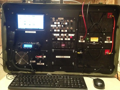
     A few 2x4's might not mean much to most folks, but to me, it means that I'll finally make a little more progress on the shack at home, which, if you'll recall, looks like this at the moment:
​
Picture
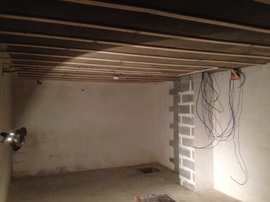
     The YL that servers as the project manager around here has given the nod to start making some additional progress in the basement project, which included getting this room framed out.  Before you know it, it might start to look like a proper shack!  Stay tuned - with any luck I'll have some progress pictures to share before the weekend is out.

Happy Hamming!
Previous: Shack Build
Next: Shack Build
0 Comments

the other radio - final

4/23/2016

0 Comments

 
post contains affiliate links
     I'm sure the purists are tired of hearing about my CB install at this point, so this will be my last post on it, but that's mainly because it's finally done!  (Is any radio project every really done?)
     I spent about an hour and a half between the last couple of evenings finishing up the install of a CB radio into the center console of my car.  To come up to speed, you may want to check out part 1 and part 2 of this project.  Okay - now that you're up to speed, all I really had left to do was to make the permanent mounting panel to replace the temporary wooden template that served for test-fitting purposes.
     At this point, the process was fairly straight-forward.  First, I put some tape onto the piece of HDPE that I had gotten from Tap Plastics to both protect it, but also so that I had something to mark on.  I then traced the plywood template onto this, and started cutting.  Here's a shot of what things looked like, part of the way through that process:
Picture
     Once all my cutting was done, I screwed the mounting bracket to this new panel.  The way that worked was actually to screw 2 small L brackets to the panel, and then I screwed the CB mounting bracket to the L brackets.  This was needed because of the angle at which the CB was mounted.
     With the part cut, and the radio in it, it was time for a quick test fit:
Picture
     If you checked out parts 1 and 2 of this project you'll know that I had installed brackets for this panel to sit on.  At this point I used my trusty tap set and drilled through the plastic, into the metal.  I then used a slightly bigger bit to drill the holes the in the plastic out just a little larger, and then I used the tap to add the threads to the holes in the brackets.
Picture
     All that was left to do was to screw the panel in place!  I also used a very thin bead of black caulk around the radio, where it passes through the opening, just to hide my not-perfectly-straight cut a little bit - I don't have a very good jig saw so cuts that I can't do on my table saw or mitre saw can give me a hard time.
Picture
     Done!  Now I've got my working CB in place, and when the center console lid is closed, it's neatly tucked away.  You may notice that there is a lot of empty space behind the radio in this panel.  With a bit of luck, and some spare $$ I hope to eventually put a screwdriver controller there for the Tarheel Antenna that I don't own yet.  One can dream, right?

     On to the next project!  Leave a comment and guess what it might be (if you read some of my other posts, you might be able to figure it out!)

     Lastly - I've been pretty please with this little CB radio - you can get them fairly cheaply through the jungle, so please check it out:
0 Comments

the "other" radio - Part 2

4/21/2016

0 Comments

 
     A while back I did a post on the initial steps that I took when installing the CB radio in my car.  I know some hams have a beef (hi hi) with CB radio, but I like having one because of the amount of highway time I have in my job.  If you want a refresher on where I was prior to this post check out my part 1 post here.  I finally had some time to continue work on this project.  It's still not done, but I made some progress on it.  The goal with Part 2 of this project was to start where I had left off, but finish up the wiring so that I could use the radio for a little bit, in it's current configuration, before cutting the final part that will make the "pretty" mounting place for the radio.
     The first part of this was to install a UHF male connector on the end of the coax in the center console.  There are about a million different theories on what the "correct" method is, what the "best" method is, and about what method Uncle Fred has been using ever since he installed his first antenna on the dinosaur that he rode to work every day.  For some silly reason, I usually just follow the directions that come from the manufacturer (they should know, right?)  For this connector the directions are to strip to the appropriate measurements, fold the shield over the reducer, screw the body on, solder the tip, solder through the holes, screw on the barrel, and call it a day.  I don't do a ton of soldering anymore, but it turned out just peachy, and I didn't get any weird readings when checking things out with my analyzer after it was done.
Picture
Picture
     I then installed Anderson Power Poles on the power lead that was waiting to be used, and on the power leads from the radio.  No pictures of that...sorry.
     With the connectors on, I turned to the antenna.  Because the NMO mount was installed on the front fender of the car, I had to bend the antenna element to make it vertical.  Basically, without doing any trimming, I measured the SWR with the antenna sticking straight out, and then I measured the SWR again after bending it to vertical to see how much bending the antenna element changed it.  I was then able to cut the bent part off, and slowly trim to length with the antenna sticking out, and then when I hit the magic spot where bending it up to vertical would make the SWR land where I wanted it, I made the bend, and presto - CB antenna!
     I also added another mic hanger, so that my ham mic and CB mic would kind of "balance" each other as they hang on the dash.
Picture

     Lastly, during a recent work trip, I got to test out the radio and it's location, so I've decided that I'm please with the mounting location, etc.  I actually got to test it out, because I heard one trucker say to another - "I wonder if that guy in the Black Fusion could get any more antenna's on his car?" to which I had to reply - "I can put as many antenna's on here as you'd like me too"  :-)  We then had a nice chat about radio's, ham radio, and what all my antenna's were for, which was great, because the HF ham bands were pretty much dead, and this way I still got to have a QSO (I just won't tell that truckers that's what we call it...)
     Since I'm pleased with it, the only thing left to do is to take out the temporary wood mounting piece, trace it onto the piece of HDPE that is waiting in my garage, and do the final "screwing down" of everything.  For now though, I'll leave you with 2 questions...
     1) How do you solder your connectors?
     2) Do you talk on CB radio? (you can call it 11 meters if it makes you feel better...)

Leave a comment and let me know!
0 Comments

What was that thing

3/22/2016

0 Comments

 
post contains affiliate links
     Don't worry, I haven't forgotten about my ongoing projects. We had been away on a family vacation, and as usual when coming back from a vacation, the job that pays the bills had some things piled up that need to be dealt with, so I ended up putting in a couple very full days.  With that thought though, here is a superfast update on where my projects stand:
  • The home shack is stalled - waiting for me to finish some work in the addition we recently (okay, maybe not so recently anymore...) did, before I can get back to finishing the basement.
  • The mobile shack is in the middle of a CB getting put in.
     I'm hoping to get the CB install finished by the end of this week, so that I can move on to "Phase 2" of the mobile install.  Once I get started on that I'll post updates, and let you know exactly what "Phase 2" is, but for now here's a teaser.  It has something to do with the 2 sheets of MDF plywood that are now sitting in my garage next to my table saw, and this thing:
Picture
     So what exactly is this thing?  About a year ago, this was a project I put together.  It is, in theory, a go-kit that I built.  If you happened to look at my QRZ profile though, you'll already know two things:
  1. I called it my "porta-station" because it was too big and heavy to "go" the way most people think of a go kit.  It's more like moving a heavy shipping container.
  2. It doesn't exist anymore, because I took it apart (insert frowny face here)
  My porta station started out as me wanting a way to have a fully functional station that I could put in my car and take with me on trips - it did work for that, it was just HEAVY.  Mainly because it had two 50ah batteries built into it, so that I could essentially run for a couple days without power.  Also built into it was a power supply, and a charge controller/DC load switcher that would automatically charge the batteries if it was plugged into AC power, and automatically run off the batteries if no AC was present.
     In the center of the beast was, from top to bottom, a small RF patch panel for switching between the various antenna connectors that I mounted across the top of the box, a row of switches for turning the various parts on and off, a small power outlet panel that had a volt meter, usb charger, and standard 12v automotive power connector, and the always important fuse block.
     The left side of the monster had (some of this stuff is internal and can't be seen in the picture) a Raspberry Pi computer with a 7" display, a mesh node, my 857d, the matching LDG tuner, a port audio patch panel, and external speaker with a separate amplifier and volume control.  Running on the Raspberry Pi was a custom command line rig control software that I wrote in Python.  Between the mesh node and the rig control software, this not only made this a porta-station, but one that I could use remotely, through a hammesh network.  The software was actually a school project (did I mention that I go to night school on top of all this other stuff?!) with the idea that I was building a drop and run emergency relay radio station, so I had a justification for putting this whole thing together - it was educational!  
     All of this goodness was build into an army surplus medical chest, in which I installed an aluminum frame (my first brazing project!) to hold all the stuff, topped off with a plywood panel to make the face.
     So why take it apart?  It was nice because it had everything in it I could need or want in a portable station.  That was also the problem.  Sometimes I didn't want all the stuff.  For some trips it was too big to take depending on what other equipment (actual work equipment) I needed to fit in the car.  I needed something more modular!
     Someone clever might be able to figure out that what I must be scheming is a go-kit version 2.  But how does that tie in to the start of this rant - my mobile shack Phase 2?  Maybe you just figured it out...
Leave a comment and let me know if you think you have an idea of what I'm up too...
0 Comments

The "Other" Radio - Part 1

3/6/2016

0 Comments

 
Post contains affiliate links

One more radio - One more Antenna

Picture
    Some call it CB.  Some call it 11 meters - tomato tomáto.  I know that for some amateur operators, CB radio is something you look down your nose at - and there are some pretty big noses to look down out there!  In reality though, many hams got started in CB, and for those of us that have jobs that required a lot of time on the road, a CB is a nice accessory.  There are times where you can find out what's up with traffic faster with the CB than with any other method.  Also, while some hams may choose not to believe it, truckers are people too, so sometimes it is just as fun to chat with them as it is to chat with hams!
     With all that being said, this is part one of my project to get my CB installed in my car.  If you have read my past posts, you may recall that I mentioned in passing that I had installed another NMO mount (this one), in anticipation of an additional antenna.  That mount is for the Browning CB antenna that I purchased from Amazon recently.  This antenna will be located on the front passenger side quarter panel.  To orient you, the NMO mount you see in the picutre is just in front of the passenger side rear view mirror.  I routed the coax through a factory grommet located just behind this point, that ends up behind the passenger side kick panel.  For a while, the coax was just coiled up there, waiting for me to have time to get on with the rest of the project.
     The next several steps happened over the course of a couple weeks, when I was able to steal an hour here and there to work.  I decided to use the center console as the location to mount the CB (I hinted at this in a post back in November when I first got the car.) Because I don't use the CB nearly as often as my Amateur radio, I wanted it somewhere that was out of the way, but was still easily accessible when I did want to use it.  To keep it clean looking, and to have a spot to mount a couple future items (like maybe a screwdriver controller....) I decided to make a panel to fit the console, to mount the radio, and any future equipment into.  
     Step one was going to be brackets to hold the panel.  I have all kinds of stuff in my metal scrap/recycling pile, so I dug through and found this, and figured I could make it work:

Picture
     After measuring the inside of the center console, I cut 2 pieces of this to length.  I then double checked where the other end of the screws would go, and screwed the two brackets into place, to act as supports for the panel that will drop in place on top of them.
Picture
     Because the space in the center console isn't square, and I needed to be able to do some test fitting, I made a template.  I started by using strips of stiff cardboard.  I cut them to length, trimmed, and fit them into place temporarily, and when they looked like a good fit, I taped them together so that I would have an outline of the console, to trace onto the next piece.
Picture
     Next, I traced this outline onto a solid piece of cardboard, and test fit that into place.
Picture
     
     Ultimately, this pattern will be cut out of the same plastic sheet material that I used to make the mounting location for the remote head for my Yeasu 857d.  For now though, I traced this cardboard template, onto a piece of scrap OSB plywood that I had, which was the same thickness as the plastic I'll be using.
​
Picture
     I actually ended up cutting several of these as I did test fits, trimmed, test fits, etc.  Once I had the basic shape the way I wanted it, it was time to decide how the radio would mount.  
When I ordered the radio (The Uniden PRO 520XL, from Amazon),  I thought it would fit in this space standing straight up, with the display basically flush at the top of the panel (I ordered a new one because my old one was too big to fit here).  
Affiliate Link
As it turned out, the dimensions on the web site, didn't include the connectors on the back of the radio.  In order for it to fit, the radio was going to have to get installed at an angle.  I cut the opening for the face of the radio, and used a couple pieces of angle bracket to attach the radio body mount to the bottom of the panel.  The idea is that with everything attached to the panel, I should be able to lift the panel, and everything attached, in and out to have access to the back of the radio, and any future stuff that gets installed here.
     But there was a problem!  The brackets I cut (the first couple pictures in the post) were wide enough that they actually got in the way of the thumb screws (more like knobs) that hold the radio body to it's bracket.  I ended up taking those brackets out, and cutting new brackets from a fresh piece of aluminum angle stock that I picked up at Lowes.  I put them in place, a little more strategically this time.
Picture
     With some better, more properly arranged brackets, everything seems to be starting to fit nicely.
Picture
     With this part of the template process done, I connected the mic cord and opened and closed the console, to make sure there was proper clearance for everything.  Luckily, center console lids are designed knowing that people are probably going to have phones, iPods, and other electronic devices in them, so there is purpose built clearance for cords to be able to exit with the console lid closed.  In my case that works perfectly for the mic cord.
     The next thing I did was to pop off the outer trim that covers the center console, so that I could drill two holes for the power and coax to enter the compartment.  With the holes drilled, I routed the coax that I mentioned in the beginning of this post, and the power wire that I mentioned several posts back.  These wires had been coiled up behind a body panel, patiently waiting for a place to go.  Now they have home!
     

That's it for Part 1

     I had to stop there, because it was time to move on to other family things.  With any luck I'll have some early mornings before everyone wakes up, or some evenings after everyone heads to bed, to finish up.  Basically, all that's left is to:
  1. Put a PL259 on the end of the coax so that it can get connected to the radio
  2. Put Powerpole connectors on the wiring that will power the radio, and on the radio's power leads
  3. Connect up the power so the radio will actually work (that helps!)
  4. Install the antenna onto the NMO mount, and tune it up
  5. Connect the antenna to the radio
  6. Do a short road test so that I can verify that I like the location and operation of the controls with the radio in this location.
  7. unhook everything, take it out, and transfer the panel from the plywood to the black plastic HDPE sheet that will make up the final product (Luckily, I have plenty left over from the other project!)
  8. Re-install everything, and call it a day!

     Depending on the timing of when I can get this stuff accomplished, part 2 may include all of these steps, or it may get broken into part 2, 3, 4...... time for stuff like this can be unpredictable when there is both a 4 year old and a 7 week old in the house.  Even though I said at the beginning of this post that I enjoy talking to the truckers on the highway, I enjoy my kids more, so time for this project plays second fiddle at the end of the day!

     Do you do any talking on Citizen's Band, or are you strictly a ham radio operator?
0 Comments
<<Previous
Forward>>

    Categories

    All
    Antenna
    Cw
    Digital-modes
    Flying-with-gear
    Home QTH
    Miscellaneous
    Mobile
    Operating Events
    Portable
    POTA
    Shack Build
    Technical


    - N3VEM -

         Welcome to my Ham Radio Blog!  This blog was started primarily to share my two concurrent shack builds - my mobile station and my home station.  Over time, this has grown to include sharing about my operations, and general radio-related thoughts that I have as a newer operator.  
         
    ​Enjoy!

    RSS Feed


    Picture
    POTA!

    Picture
    Proving that hams do indeed still build stuff!

    Picture
    100 Watts and Wire is an awesome community, based around an excellent podcast. 

    Archives

    September 2020
    July 2020
    January 2020
    September 2019
    August 2019
    July 2019
    June 2019
    May 2019
    March 2019
    January 2019
    December 2018
    November 2018
    October 2018
    September 2018
    August 2018
    July 2018
    June 2018
    May 2018
    April 2018
    March 2018
    February 2018
    January 2018
    December 2017
    November 2017
    October 2017
    September 2017
    August 2017
    July 2017
    June 2017
    May 2017
    April 2017
    March 2017
    February 2017
    January 2017
    December 2016
    November 2016
    October 2016
    September 2016
    August 2016
    July 2016
    June 2016
    May 2016
    April 2016
    March 2016
    February 2016
    January 2016
    December 2015
    November 2015


Picture
Copyright © 2015
 Vance Martin is a participant in the Amazon Services LLC Associates Program, an affiliate advertising program designed to provide a means for sites to earn advertising fees by advertising and linking to amazon.com.