NOVEMBER 3 VICTOR ECHO MIKE
  • Blog
  • Events and Activations
  • Diversions
  • About
  • Gallery
  • Contact
  • Links
  • Subscribe
  • Search
  • Blog
  • Events and Activations
  • Diversions
  • About
  • Gallery
  • Contact
  • Links
  • Subscribe
  • Search
NOVEMBER 3 VICTOR ECHO MIKE

ham radio Projects and musings from a (Relatively) new operator

Absolutely Awful Antenna

6/16/2016

3 Comments

 
     Before getting started, I have to qualify the title of the post with the fact that I absolutely abhor alliteration.......maybe?  Anyway, it has been some time since my last post.  I haven't had much chance to play radio in the last several weeks because, as many of you know, most of my operating is mobile.  The problem was, I was without my vehicle for a while because it once again started doing the thing where it decides to stop running while I'm going 60mph on the highway...fun.  In the middle of that I had to make a trip out of town, so my radio activities were limited HT stuff.  It still lets me talk to folks, but doesn't make for as much entertaining reading.
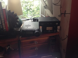
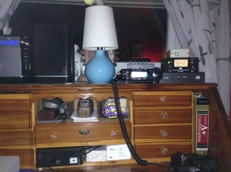
      Anyway, to get on with the topic of this post - some of you may remember reading about my gutter antenna in an earlier post.  Since my vehicle was going to be gone for a bit getting repaired, I decided to take my radio gear out, so that I could set it up and play with it at home.  With 2 little ones in that house, even that is hard to do, but I eventually threw everything back on my desk, and hooked it up to the Gutter-tenna.  
Picture
     So, according to the purists, here's where I tell you the antenna is awful - it has no radials, just a ground rod, which isn't even copper (it's a piece of rebar!) I tune it "in the shack" and not at the base of the antenna, etc. etc. etc.  According to all the things you "should" do for an antenna, I might as well be transmitting into a dummy load, but you know what - it works anyway!  Which is the whole point here, even this absolutely awful antenna lets me get on the air, make some contacts, and play around.  Stop listening to what everyone says you should do, and just throw some metal in the air (or connect a wire to the metal you already have in the air...) and play radio!  ​       
     So, since my gutters are the most antenna I will have up at home for the immediate future (not because of homeowners covenant, but because of a much more important one...) I decided that I could at least slowly start "upgrading" my gutter-tenna.  I'll post here when I get to make my tweaks every now and then, so here's the couple tweaks I just made:
     Radials!!!
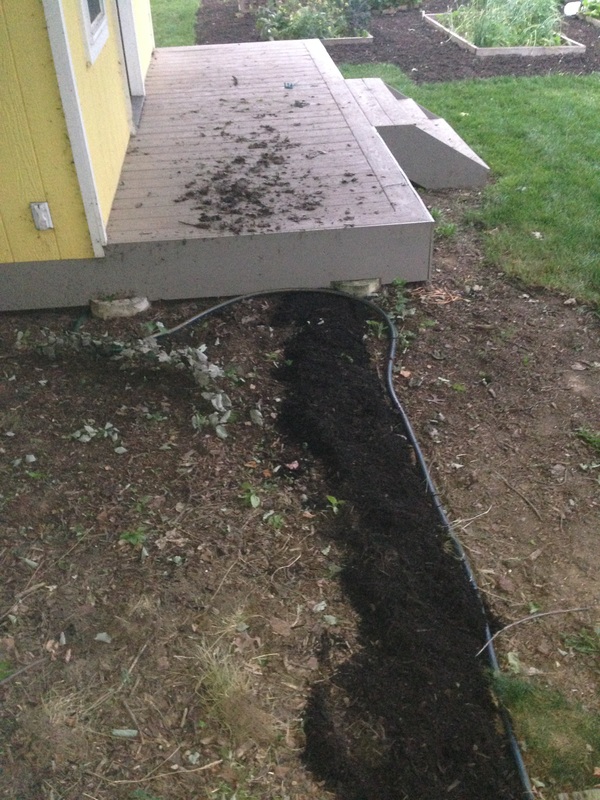
     We've been working on mulching, and because of the arrangement of flower beds, where the downspout I connect to is, etc.  I realized I could throw down a couple radials, and as we finish mulching, they'll be buried.  I only put down 2 for now, but I figure if I plant radials every so often as we work in the gardens, yards, etc.  I'll slowly over time build up a proper radial field, and maybe the YL won't even notice it going in (okay...so she already knows the plan...she caught me, in her own words, "skittering around out there" so I was obliged to let her know what I was up to :-)

     These first 2 radials I put down are 50 feet long.  One runs along the house, and goes around the front corner, so it is tucked in the back of the flower beds.  The other runs through a mulched area under a big tree, and then under the play house I built in the back yard a couple years ago.  Even though we're not done mulching, I threw mulch down over the radial that runs towards the back, just to hold it down while we mulch the rest of the area.  Just do me favor and ignore the dirt on the playhouse porch - we just had a decent wind/rain storm and all the stringy dirty stuff came down from the maple trees and blessed us with it's presence all over our property.
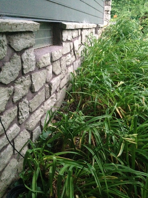
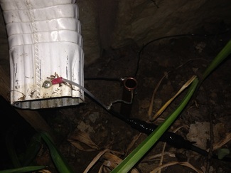
     I also changed the feedpoint just slightly - I pulled out the rebar and replaced it with a piece of copper pipe I had in the garage.  This is still temporary, but at least it won't rust away while I get the more permanent feedpoint put together.  For now the pipe just has a hose clamp making a mechanical connection to the braid of the coax and the two radials.
Picture
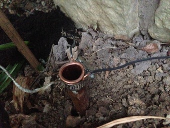
     The connection to the downspout is almost as fancy (and PS...can't last long - copper to aluminum by it's nature is temporary - there's a fancy word for it I forget [ed. Galvanic Corrosion - thanks to the social media community for reminding me!], but the "mismatch" of metal types will eventually make this connection rust a bit, but that's okay - I only need it to last while I "fancy it up" a bit!)
Picture
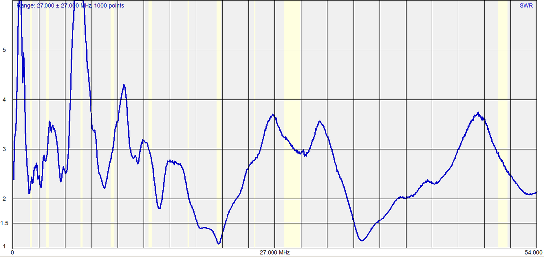
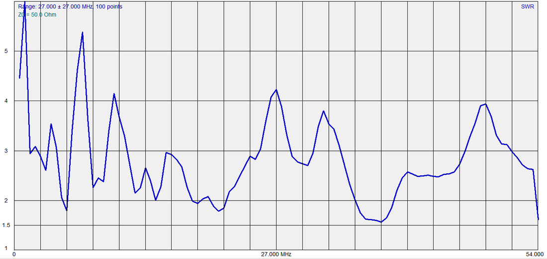
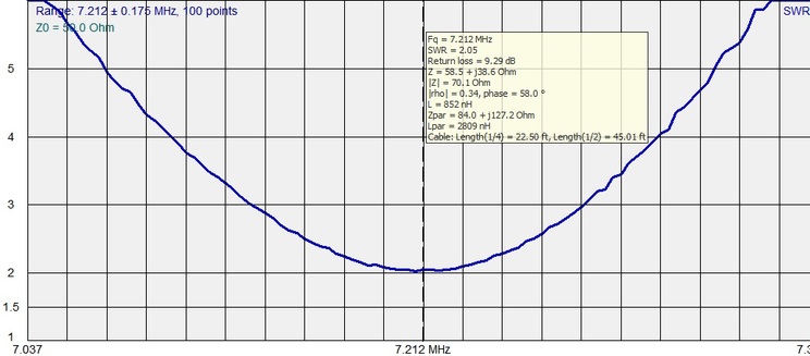
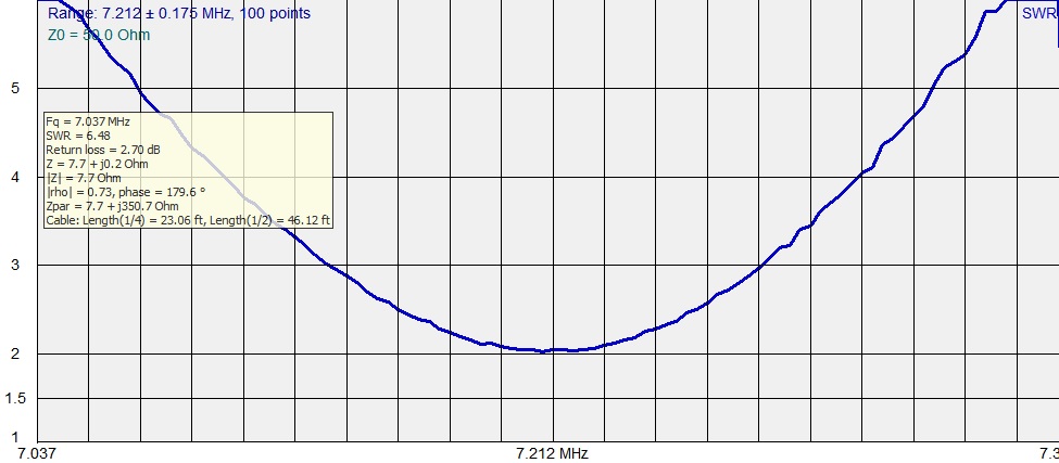
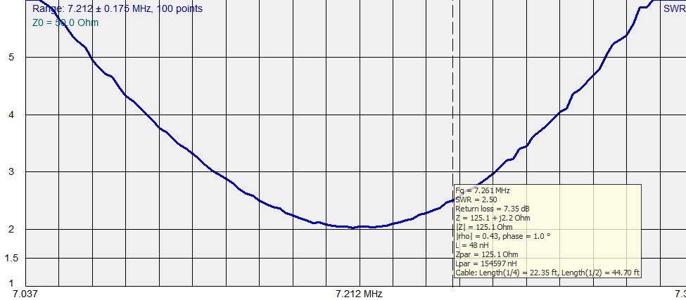
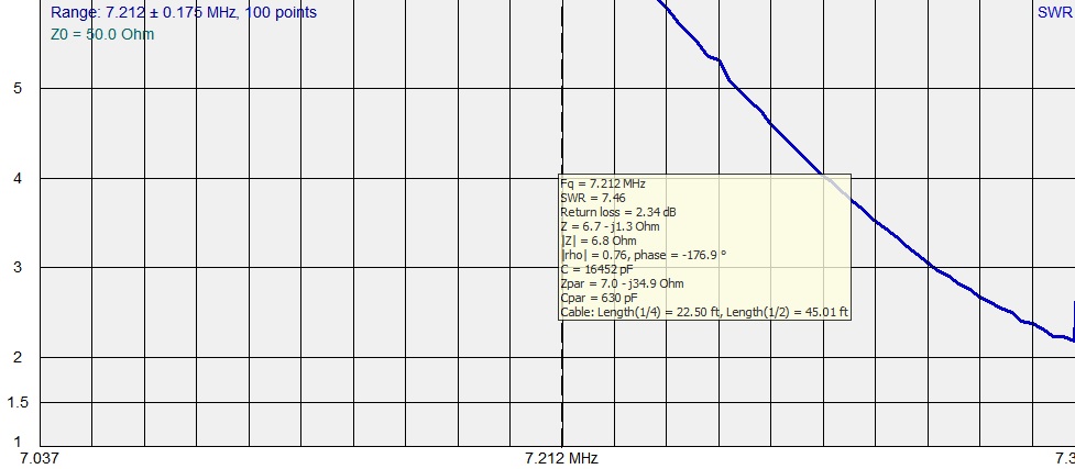
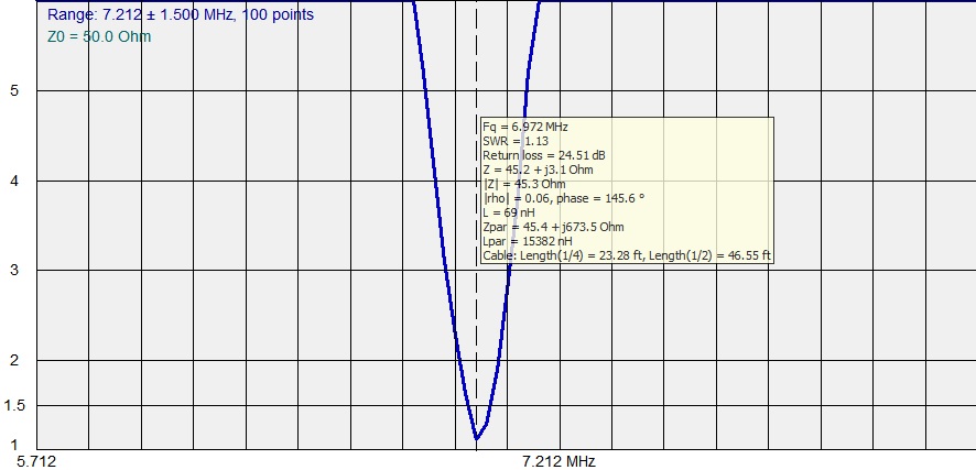
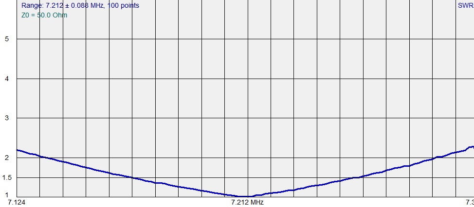
     So, at the end of the day, my Absolutely Awful Antenna isn't really that bad!  It works, and oh, by the way, has a very tuneable SWR of around 3:1 or less in most of the Amateur Bands (of course, 40 meters is the one that's completely out of wack......oh well....)
Picture
     So what radio "rules" do you break in order to get on the air and enjoy the hobby?  What has worked that surprised you, and what didn't work that by all accounts should have?  Leave a comment and let me know!
3 Comments

little black box

5/12/2016

0 Comments

 
     Oh no!  there are spies trying to listen in on the phone calls at my hotel!
     I'm not a conspiracy theorist, so when I saw this thing in my hotel room connected to the phone I figured there was a legitimate reason, but I know some people would probably freak out!
Picture
     So what does the secret black box in a New Jersey hotel room have to do with Ham Radio?  Well - Like any other good ham, when I saw what I supposed was an electronic device connected to a communication device, I took it apart!  What do you think it was?
     Ta-da!  RF Choke!
Picture
Picture
     Now that we know what it is, we don't have to panic - the foreign spies apparently aren't interested in land line conversations from a hotel in NJ after all - we can breathe a sigh of relief.  With that being said, I guess most normal people wouldn't have done this, they probably would have just looked at the sticker on the front of the device and Googled it - but that's no fun!
Picture
     Based on the frequencies it says it is for, I would have to assume that there are some strong AM broadcast signals in the area that were causing problems in the audio for the phone handsets, because these were on both the phones in my hotel room, and the phones in the lobby, etc. that I could see.  I didn't notice anything on the ham bands as I was driving into the area, but then again, the only ham band that falls in the range of this device is 160 meters, which I don't have capabilities for in my car.  Maybe a ham from Secaucus will stumble onto this blog entry and let us know if there are some strong AM signals in the area that could be behind all this business.
     What would you do if you saw a funny black box connected to the phone in your hotel room?  Leave a comment and let me know!
0 Comments

in The Gutter

4/27/2016

5 Comments

 
If you go all the way back to the beginning of this blog, you can see the current state of my home shack. If you need a refresher, here it is again.
Picture
     Due to the hecticness (is that a word?) of life, and some other home projects that needed finished ahead of this, I haven't had time to dig into the work down here yet - but I will soon!​
     Even though life is busy, I still like to play radio in the house every so often. If that urge strikes and I can't fight it, I bring my stuff in from the car and set up like this:
Picture
When I do this, the antenna I use as a temporary one is my gutters. Right outside this window is the downspout that goes up from the basement to the roof, and then the gutter runs the length of the main part of the house, about 32 feet. This means that between the downspout and gutter, I basically have a 60ish foot inverted L antenna, with the vertical part being about half of it. This works out to about 1/2 wave on 40 meters.
     When I decided to use this I knew it would be temporary, so I just pounded a 6 foot piece of rebar I had into the ground at the base of the downspout. I put a ring terminal on the center conductor of the coax and screwed that to the bottom of the downspout, and then used a hose clamp to attach the shield to the rebar.
 I make an ugly choke out of a few turns of the end of the coax, and connect the other end to my LDG tuner, and call it a day. Not nearly as effective as radials and proper matching would be, but it gets me on the air temporarily.
     So, all of this was to bring you here: Gutter's can make pretty darn good antenna's! 
Good enough that I'd consider burying some radials, putting in a proper ground rod, and making the coax connections a little more weather proof.  I made some contacts with good reports, and low power almost right away, so I decided to measure my gutter antenna using my analyzer.  Here's the graph:
Picture
     This graph covers from 0 to 54 MHz, and almost all of it is under 5:1 SWR, so the LDG tuner that works with my radio can match it all just fine.  Here are where the bands land:
  • 160m is all right around 3:1
  • 80m varies from 2.5:1 to 3.5:1 
  • 40m is the worst ranging from 4:1 to 5.3:1 (go figure!)
  • 30m is all just under 4:1
  • 20m is all between 2:1 and 2.5:1
  • 17m is about 2:1
  • 15m is all between 1.8:1 and 1.81:1
  • 12m is between 2.8:1 and 3:1
  • 10m is between 2.7:1 and 3.3:1
  • 6m is between 1.6:1 and 3.3:1
     In addition to the relatively low SWR, there are a several spots that are nearly resonant - several of those aren't in the amateur bands, but a couple are:
  • 3.780MHz
  • 28.080MHz
  • 51.840MHz
     So if you actually read the whole way through this - what do you think?  Are you gonna hook up to your downspouts and gutters and see what magic you can make happen?  I know at least one of the local hams in my area uses his gutters from time to time, and I owe him a visit so that we can hook up the analyzer to his guttertenna and see how it charts out.  Leave a comment and let me know your thoughts!
5 Comments

Revisiting the unun

3/20/2016

2 Comments

 
     If you look back at my post about the MFJ unun that I am using to help match my Hamsticks, you might see that I got a couple different bits of feedback.  The basic question I had asked is this:  When matching an antenna is it better to start at lowest SWR or Resonance?  The method I ended up using that I described in that post was starting from Resonance - mainly because that seems to be the suggestion from K0BG on his website - plus it had some other advantages that made me lean towards that method.
     Like many things, there is a lot of back forth when questions like these come up.  There are things like questions about how much it really matters when you consider how compromised a mobile antenna is, where is the matching device located, how long is the coax, etc.  With that in mind, I'm considering a small experiment:
     Because the Hamsticks use the whip at the top for tuning, the matching I did, starting from resonance, is a combination of the setting on the matching unit, and the length of the whip.  I could unscrew the whip part, and set it aside, and screw in a separate whip, and do the whole matching process again, but starting from low SWR.  Doing this would give me a way to compare the two methods because I could quickly swap the Antenna back and forth between one matched starting from resonance, and one matched starting from low SWR.  I have an inexpensive meter that I can use to measure field strength - it doesn't give absolute values, but I could set it based on the first antenna arrangement, and then compare the second antenna.  The process would go like this:
  1. Put in the whip matched from resonance, and set the MFJ matching unit to the appropriate setting.
  2. Put the field strength meter some set distance from the antenna (15 feet?)
  3. Transmit a carrier on low power - maybe 5 or 10 watts
  4. Calibrate the field strength meter to mid-scale
  5. Switch to the second whip, matched from low SWR, and set the MFJ matching unit to the appropriate setting.
  6. Transmit a carrier on the same low power setting as step 3
  7. Compare the reading on the field strength meter
     Does this sound like it would be a reasonable comparative test, or am I missing anything important?  I think by following these steps I'll have a "controlled" experiment, and I'll have a fairly objective way to measure the results, other than just asking someone "how do I sound now?"  Thoughts?  Comments?  Should I go for it?
2 Comments

Transformers 2.0

2/4/2016

12 Comments

 
Post contains affiliate links
     After a very cold Winter Field Day, the weather got mild fast, and it rained hard for a day, so our snow is almost gone, and the temperatures are back above freezing.  As promised, this means that I am now revisiting the unun that I recently installed in my vehicle, to do more antenna tuning.  In a previous post I explained the slight lack of clarity in the directions that came with the unit, and talked about my hunch about a better way to go about the process.  
     I basically decided to "start from scratch" so that I could talk you through what I did, what measurements I took, etc.  With that being said here we go.......

Step 1?

     The directions that come with the unit I purchased tell you start by tuning for lowest SWR without the unun in line.  Since I was working with my 40 meter Hamstick, I decided to target the center of the voice portion of the band (I don't plan on doing digital modes and such while driving!)
     The analyzer I have is the RigExpert AA-54, so I exported the charts to my computer after taking my readings - it was my first time playing around with this feature.  I didn't realize how powerful it was!  As I tune the rest of the Hamsticks I might take my laptop along out and use it in the "live" mode.  After tuning for lowest SWR at 7.212 this is what I had:
Picture
    Some interesting notes on this.  The range of the graph covers just slightly more than the 40 meter band.  The SWR at its lowest is 2.05:1 which will work, but isn't great.  The 857d doesn't like SWR levels more than 3:1 per it's manual, so that puts the 3:1 frequency range at 7.138 to 7.282 which is a bit short of covering the whole voice portion available to Extra's.  
     Also, take note of the subset box.  You can see that at the lowest SWR the impedance of the anteanna is 58.5+j38.6.  In my mind this seems like a funny place to start matching from.  My gut (Elmer's jump in if I'm wrong!) tells me that I should be starting from a point where the antenna impedance is pure resistance, i.e. starting from a resonant point, instead of a low SWR point.  I actually had two of these points "relatively" close to the low SWR point.  One of the neat things with loading the data from the analyzer onto the computer is that I can show you those two points on the same graph:
Picture
     The first resonant point, above,  is actually just below the lowest frequency on the scale.  At the very bottom of the scale, we're almost there at 7.7 +j0.2 Ohms.  This would be a 6.48 SWR at resonance.  
     The second resonant point, below, is up at about 7.261MHz (thats as close as the resolution of this graph will show anyway). At that point we've got an impedance of 125.1 +j2.2 ohms for an SWR of 2.5:1 which isn't horrible.  
Picture
    So where should I tune my antenna to, before starting my matching?  

Step 2

     I decided to go with the point where the impedance is 7.7 +j0.2 Ohms, primarily because the unun I bought assumes your antenna side is less than 50 ohms, and matches from there.  It would work the other way just by reversing the input and output, but this means that every time I switch to the 40 meter antenna, I would not only have to change the unun setting, but I would also have to disconnect the coax from both sides, and swap them (or build a switch to accomplish the same thing.)  It seemed easier to just tune to the point where I don't have to re-wire my antenna just to change bands....
     After re-tuning so that resonance was at 7.212 my chart looks like this:
Picture
     From an SWR standpoint - awful, but I'm still hanging my hat on the fact that it's better to start at resonance and then match from there.  This however, is where the directions that come with the unun could leave you wanting.  At this point they say just click through the setting and use the setting with the lowest SWR.  this makes it sound like one of these setting ought to get you close to to 1:1.  This isn't the case.  I ended up re-graphing on each setting, and choosing the setting that had the lowest dip, the closest to 7.212.  This was actually relatively far from where I was.  I had to graph with a really wide frequency range to find the setting with the lowest dip:
Picture
     So after doing these steps, with the unun in line, the lowest SR is 1.13:1, but all the way down at 6.972 MHz.  Time for the final Step.

Step 3

     So, for the final re-tuning of the antenna - re-tuning to get that 1.13:1 SWR point up to 7.212 MHz, which meant shortening the antenna a bit.  After a number of consecutive shortening and re-measuring activities, I ended up here:

Picture
     So after all that, was my thought process sound, and is my final result a good one, or have I unknowingly made this way more complicated than it needed to be, and screwed something up without realizing it?  Hello?  Is anybody out there?
     Oh - on a final note, I re-tuned my 75 meter Hamstick too.  Resonance was very close to low SWR on that one, so the adjustment's weren't nearly as extreme, or as exiting, so I didn't bother sharing the graphs of those.
12 Comments
<<Previous
Forward>>

    Categories

    All
    Antenna
    Cw
    Digital-modes
    Flying-with-gear
    Home QTH
    Miscellaneous
    Mobile
    Operating Events
    Portable
    POTA
    Shack Build
    Technical


    - N3VEM -

         Welcome to my Ham Radio Blog!  This blog was started primarily to share my two concurrent shack builds - my mobile station and my home station.  Over time, this has grown to include sharing about my operations, and general radio-related thoughts that I have as a newer operator.  
         
    ​Enjoy!

    RSS Feed


    Picture
    POTA!

    Picture
    Proving that hams do indeed still build stuff!

    Picture
    100 Watts and Wire is an awesome community, based around an excellent podcast. 

    Archives

    September 2020
    July 2020
    January 2020
    September 2019
    August 2019
    July 2019
    June 2019
    May 2019
    March 2019
    January 2019
    December 2018
    November 2018
    October 2018
    September 2018
    August 2018
    July 2018
    June 2018
    May 2018
    April 2018
    March 2018
    February 2018
    January 2018
    December 2017
    November 2017
    October 2017
    September 2017
    August 2017
    July 2017
    June 2017
    May 2017
    April 2017
    March 2017
    February 2017
    January 2017
    December 2016
    November 2016
    October 2016
    September 2016
    August 2016
    July 2016
    June 2016
    May 2016
    April 2016
    March 2016
    February 2016
    January 2016
    December 2015
    November 2015


Picture
Copyright © 2015
 Vance Martin is a participant in the Amazon Services LLC Associates Program, an affiliate advertising program designed to provide a means for sites to earn advertising fees by advertising and linking to amazon.com.